How to build guitar effects pedals
A step-by-step guide to assembling your first stompbox
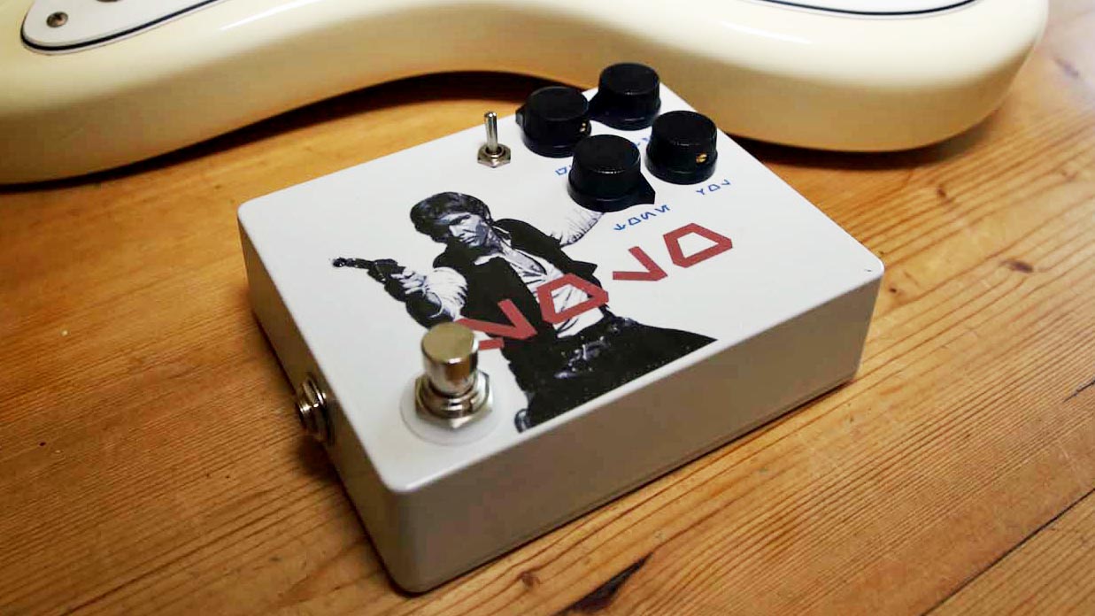
Basics
There are a number of motivations behind building your own guitar effects pedals - cost, classic circuits being out of production, or just curiosity about just how these magic boxes work.
Contrary to what you may think, or what some boutique builders might have you believe, if you have a basic understanding of electronics and a patient disposition, most effects should be well within your reach as a builder.
If you don't have a grounding in the essentials, then do not fear - we'll go over the basics you'll need in this piece, and you can then expand on this foundation with some simple web searches.
Hello vero
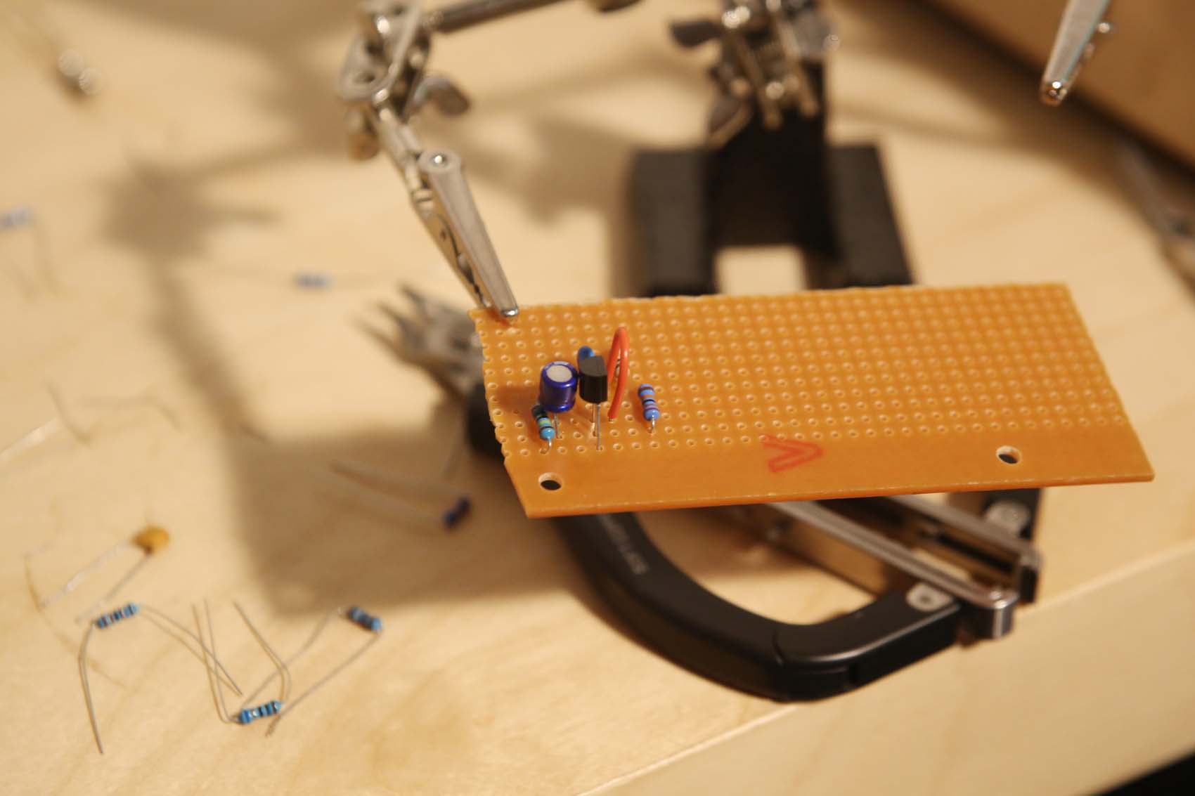
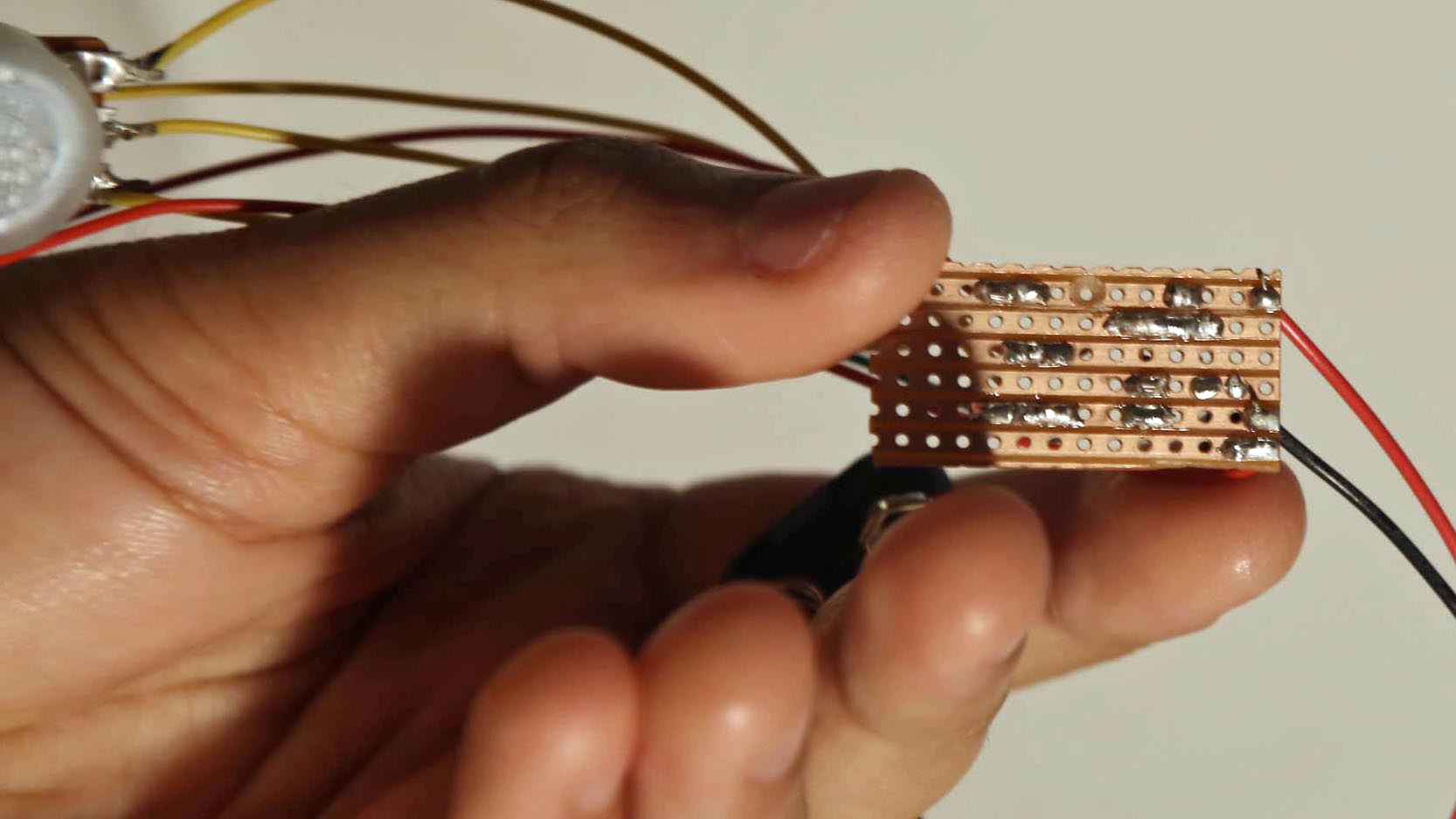
The pedal in the picture is a one-off prototype for a fuzz. You'll notice that it is not on a coloured PCB, or Printed Circuit Board; rather, it's on vero board, a cheap way of building circuits once you understand the basics.
Many websites will provide you with vero board layouts of popular effects, so it's a useful build style to learn if you don't wish to spend a lot of money on kits or prefabricated PCBs.
However, vero is notoriously difficult to debug (troubleshoot), and so it's strongly recommended that you build some pedals using prefabricated boards or kits to get your bearings before you dive in to a large vero project.
In this series, we’ll lay the groundwork how to get started, and build a simple fuzz pedal on vero. Ready to get started? Let's first have a look at the tools and parts you'll need.
Tools
The most important thing you'll need is a basic tool set - any one for about £10 from a DIY retailer should do. The main tools you'll reach for again and again from here are precision screwdrivers, an adjustable wrench, a craft knife and needle-nose pliers.
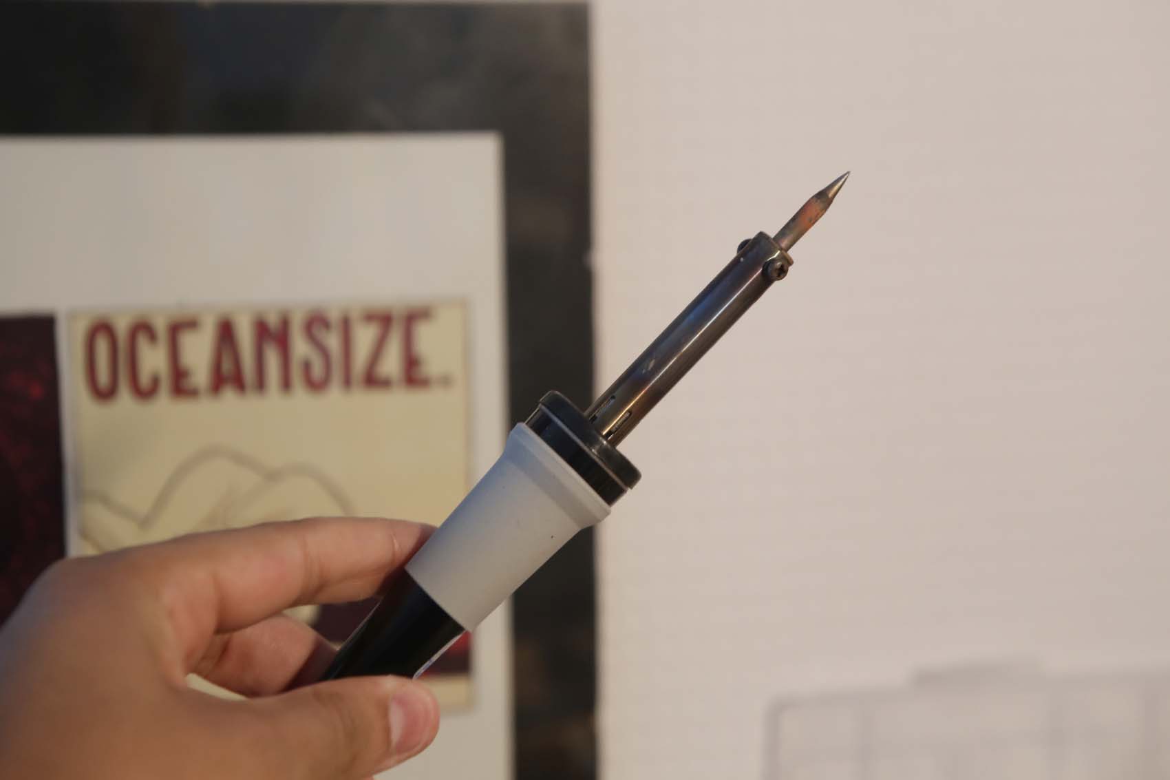
Specialist tools required can be a rabbit hole, but the basics are a soldering iron, reverse-action tweezers, wire cutters, solder, solder pump, iron cleaner, helping hands and a multimeter.
If that sounds daunting, don't worry. A quick explanation of the more unusual items follows.
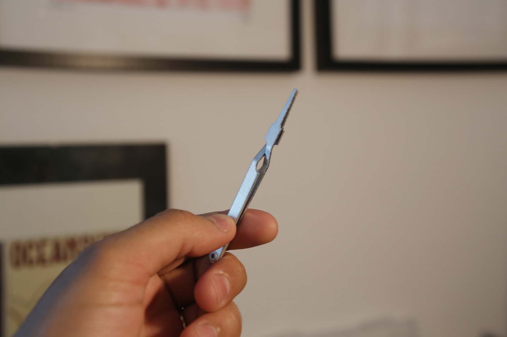
First, reverse-action tweezers are closed at rest, meaning you can clip them to something, let go and they stay in place. These are useful as a heat-sink for sensitive components.
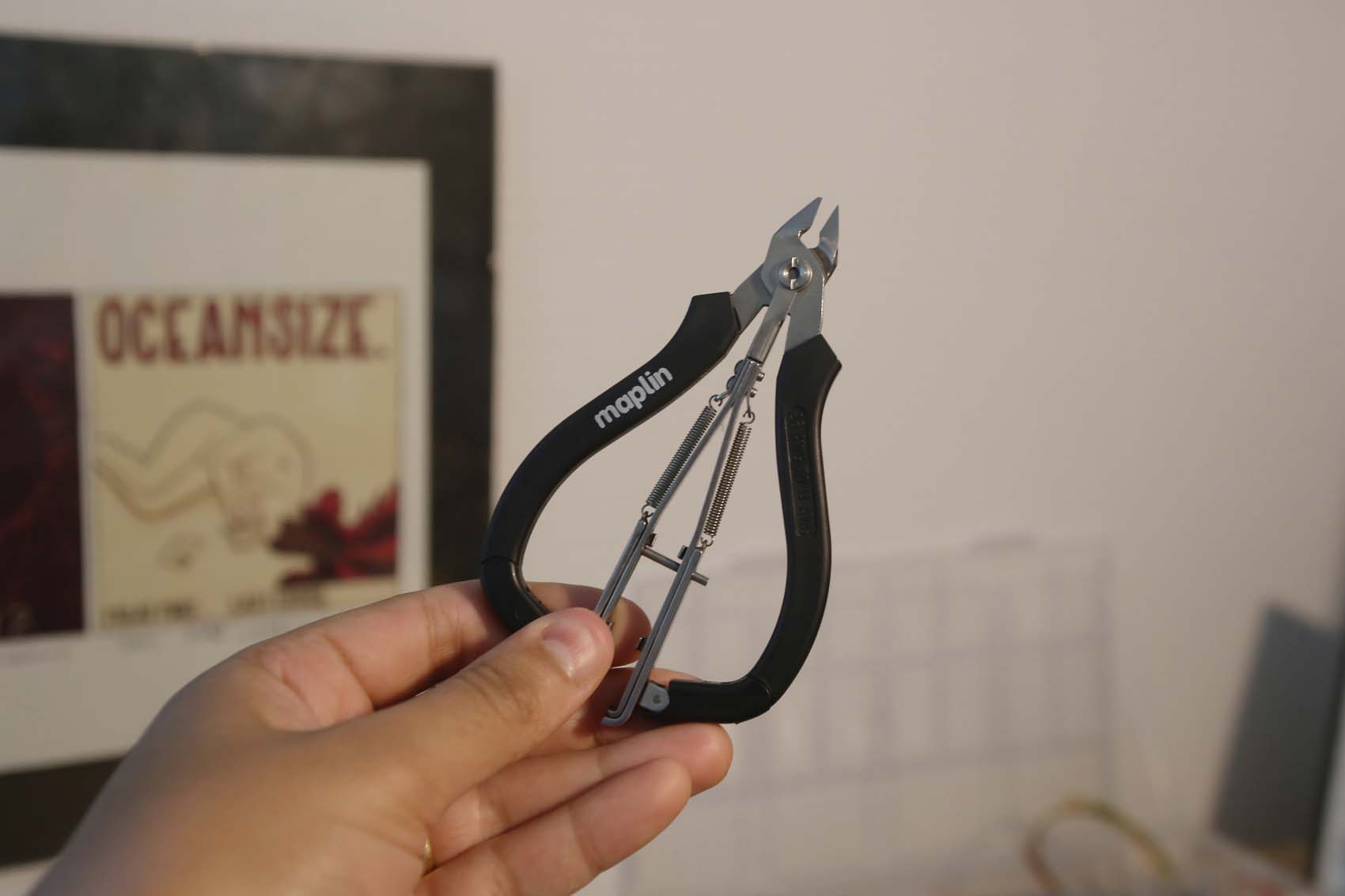
Next, wire cutters. You can get a cheap pair anywhere, but they are probably your single most-used tool, so consider getting a pair of these brilliant combined cutter and strippers from Maplin.
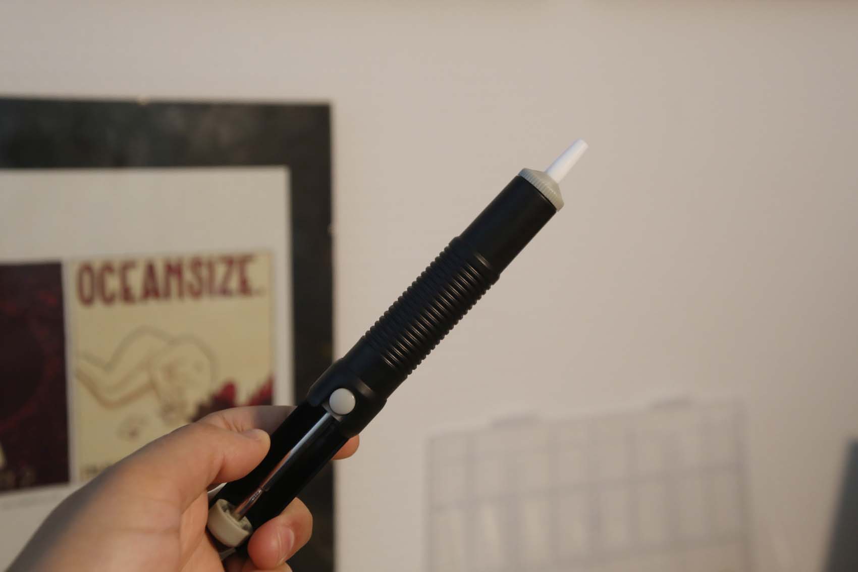
A solder pump is for something you hopefully won't have to do - desoldering components. It sucks up heated solder so a component can be removed from its place.
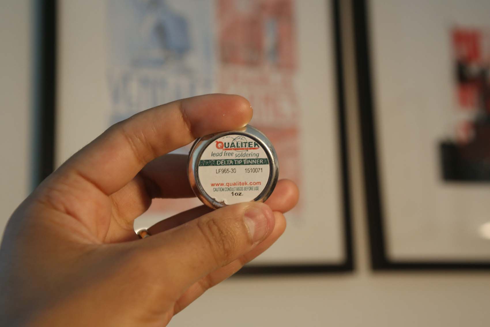
Iron cleaner, also known as tip tinner, is usually a solid block of solder and flux in a tin that will help maintain your iron, and is a life-saver compared to manually 'tinning' your iron.
Finally, helping hands are a pair of clips with a magnifying glass and heavy base that mean you can have both hands free to work on your project. These will save you hours of frustration.
You may also want to make yourself an audio probe; we'll cover doing that a little later.
Parts
If you've ever opened up a non-digital pedal - for example, a fuzz pedal - there's a good chance you will have seen a dizzying array of tiny components. However overwhelming this looks, however, there's probably only a relatively small number of component types present - and on boutique or older pedals, these should be even more clearly identifiable.
For our purposes, there's only a few main ones to be aware of, and you've probably heard of them before.
Resistors
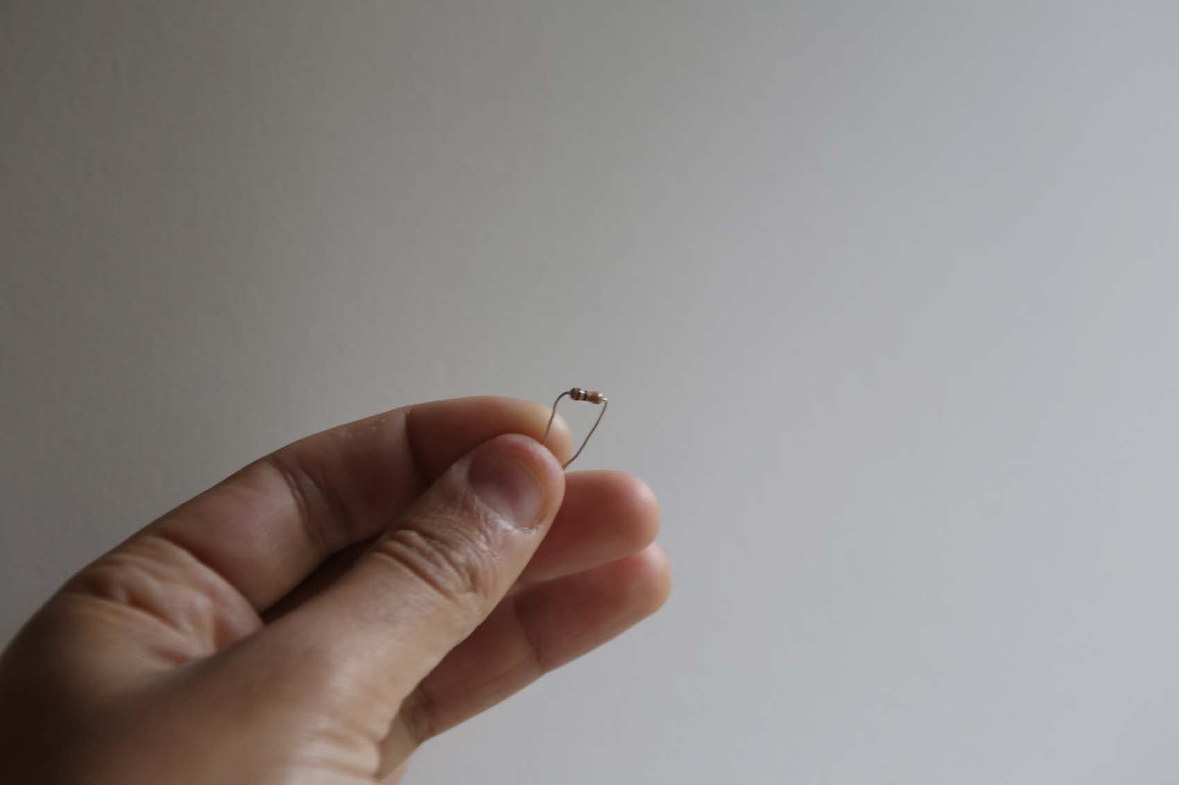
First up, there's resistors. They are passive components, which means their controlling function is linear. Resistors are used to resist the flow of current and create the correct operating conditions for certain components.
They are colour-coded with either three or four bands to indicate resistance, and then a band to indicate the tolerance of the part. For most cases, you can ignore the tolerance band, especially if using metal film resistors.
Capacitors
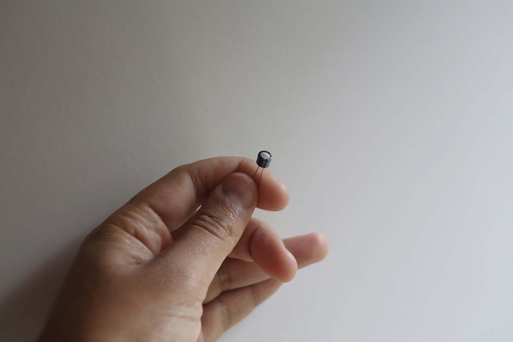
Capacitors are another passive component that crop up a lot in audio circuits. They come in two types: radial and axial. Axial have their connectors at each end of the 'barrel', and radial have both legs on the bottom.
The key thing to know about capacitors is that they can be polarised. If unpolarised, they can be placed either way around, but if they are polarised, the schematic will indicate which way around the part should fit.
Generally speaking, the positive leg, or anode, will be longer, and the cathode will be shorter; normally, there is a white, grey or silver stripe on the cathode side as well. This is important as they can blow up with a 'pop' if placed the wrong way around.
Capacitors are useful as they block DC current, which is good for eliminating power supply ripple, and splitting - or 'decoupling' - circuits into isolated parts that can be reasoned about and controlled more precisely.
The Big Muff, for example, has a circuit that is much more carefully decoupled than a Fuzz Factory, which is why it is easier to reason about the interaction of its controls.
Potentiometers
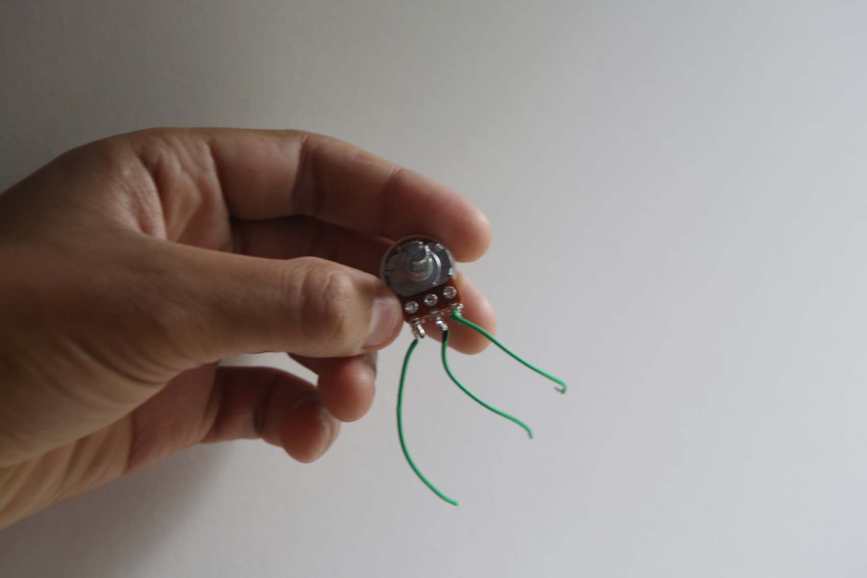
Potentiometers, or pots, are what form the controls of a pedal. They can either be wired as a rheostat, or variable resistor, or as a true potentiometer. A potentiometer moves a resistance to allow more or less signal from pins one or three to pass through pin two - the 'wiper' - while a rheostat controls only the resistance to current.
A rheostat, for example, is used to control supply voltage in the Fuzz Factory circuit - the 'Stab' control - while a potentiometer in the Big Muff serves as a tone knob by selecting between a high- and low-pass filter that are attached to pins one and three.
In order to count the pins, place the pot flat on the desk, point the pins toward you, then count left-to-right. Left is one, right is three.
Diodes
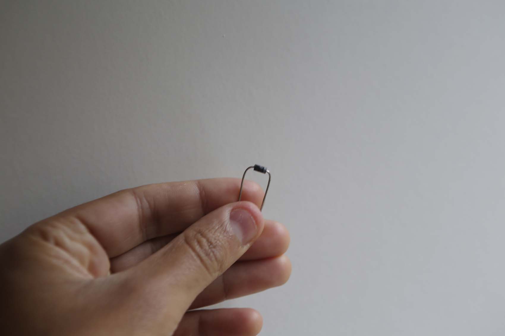
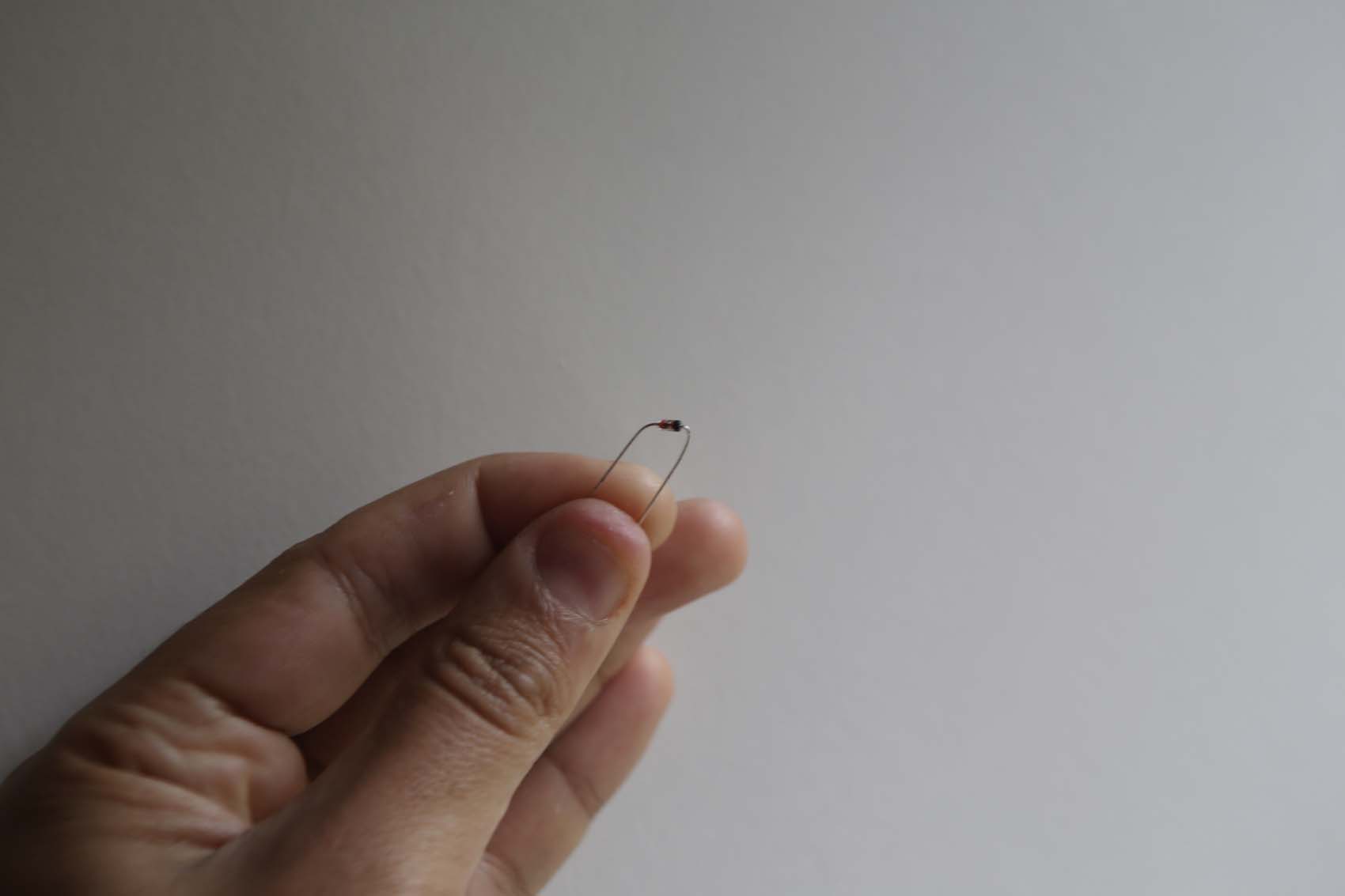
Diodes are polarised components that only let current flow in one direction. They are often used to clip a waveform for audio effect, for example in the Big Muff or ProCo RAT circuits, where diode clipping stages are the basis of the distortion sound.
They are also used to rectify waveforms from time-varying Alternating Current (AC) to time-varying Direct Current (DC). This is important, as a guitar signal from magnetic pickups created by induction is AC, but most components require DC.
LEDs are a type of diode, though like other diodes, they will often need a resistor between them and the power supply to avoid being damaged. They are also sensitive to heat, so need heat-sinking when soldering.
Transistors
Finally, there's transistors. Transistors are active components with three legs - the collector, base and emitter - and they come in two polarities, PNP and NPN. In audio circuits, these are primarily used as amplifiers, as a small current across the base can be used to regulate a larger current across the other two legs.
Early transistors were made of Germanium, but this has been superseded by Silicon in most cases outside of audio. The PCB, schematic, data sheet or a multimeter can be used to determine which legs correspond to collector, base and emitter.
That may seem like quite a lot to take in, but don't worry - these things will become clearer in time. For now, just remember which components are polarised and which have specific pin layouts. Most schematics will help you by laying out the exact pin or leg arrangement as well.
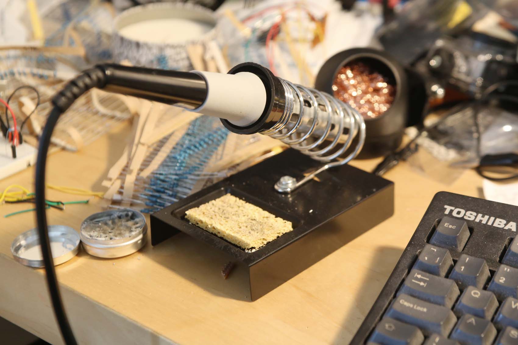
Soldering iron
You may think a soldering iron is self-explanatory, but there are some useful tips to keep in mind for getting the best performance out of your iron.
Before soldering, you need to 'tin' your iron. This is for maintenance, and to ensure solder that meets the hot tip can flow.
The tip of your soldering iron is hot enough to melt metal, so it oxidises quickly when up to temperature. This means you need to clean it before making each connection.
Your soldering station should come with, or have space for a wet piece of sponge - always wipe the tip on this before attempting a connection. After wiping, the tip of the iron should be shiny.
If after wiping, the tip of your iron is not silvery in colour, you may need to re-tin it. You'll need to do this often, but if you have some tip tinner in a pot, it's as simple as dipping the tip in, then wiping the excess away on your sponge pad.
Solder on
There are two types of solder, broadly speaking: lead-free and leaded. In Europe, you're most likely to see lead-free, which has rosin in it for flux. In case you're curious, yes, that is the same rosin that you rub into violin bows.
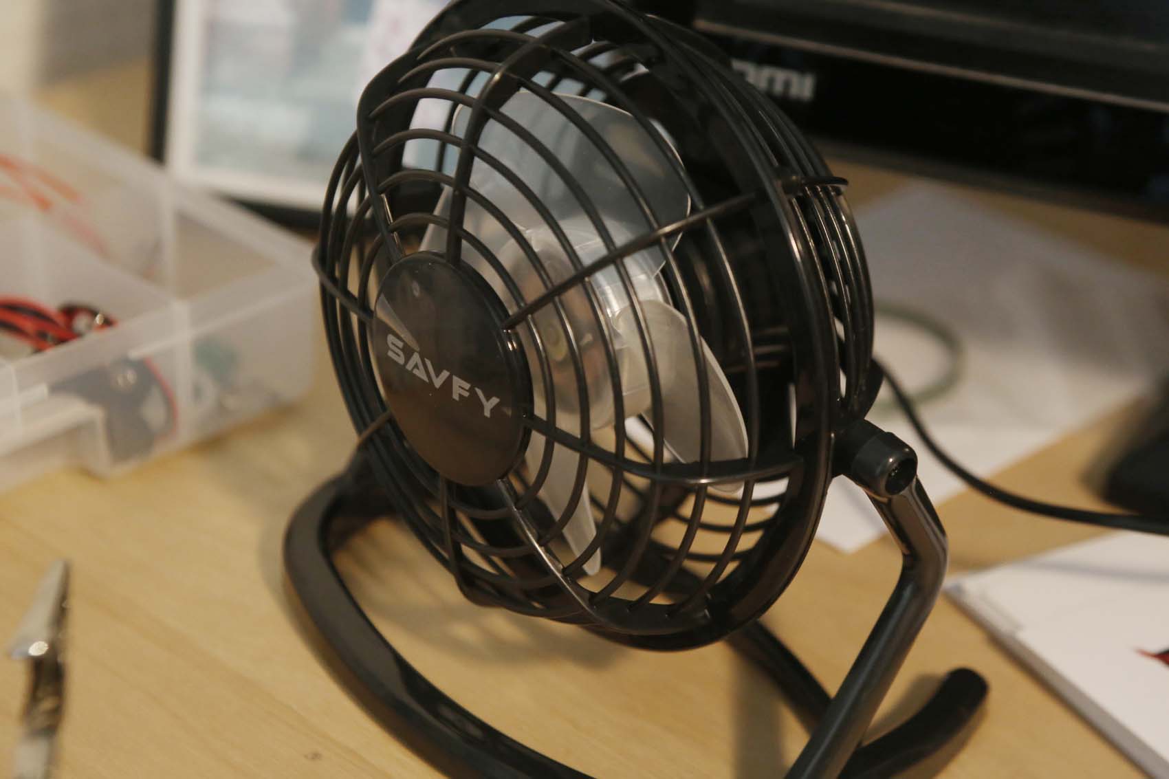
If you do have lead solder, the melting temperature is much lower, making for easier connections, but remember to wash your hands after you're done, and not to touch your face while working - lead is poisonous. With lead-free solder, the rosin lets off toxic smoke, so use a small desk fan to blow it away from you while you work, and open a window if possible.
To make a connection, put the component in place, and bend its legs so it stays in place - you'll need both hands to solder it. Touch the clean tip to the pad if on a pcb, or the hole if on vero, and the lead of the component you are soldering for about a second.
Touch the solder to the very tip, so it is mostly underneath it, then withdraw the solder once it flows under the hot tip. Keep the soldering iron in place for a further second to ensure the solder flows into the hole and makes a good connection.
Bear in mind that diodes and transistors are heat-sensitive, so heat-sink them and make confident connections where the iron is in contact with the component leg for a couple of seconds at most.
As always, though, practice makes perfect.
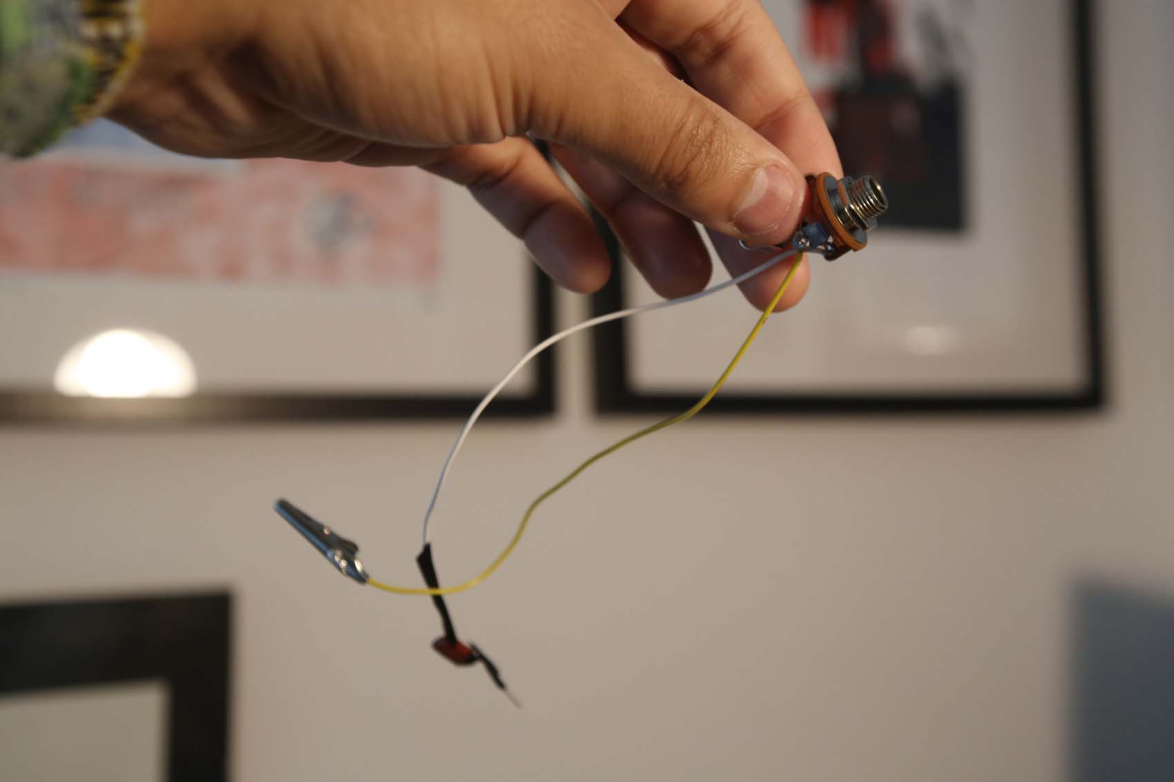
Audio probe
As a quick practice before moving on to an actual circuit, we're going to construct a simple audio probe.
The parts you need are:
- Two lengths of wire
- Standard Neutrik jack input
- Non-polarized 0.1uF (100nF) axial capacitor rated between 16V and 600V
Most people getting into pedal building have a friend that will helpfully gift one of these to a newbie (thanks, Jonny) - they make debugging audio circuits that bit easier.
To use it, plug your instrument into the jack in for the circuit you're building, and plug the amp end into the jack of the probe. You can then use the lead from the capacitor to check signal by touching it against points in the circuit.
The capacitor is not optional - it's there to decouple and protect other things later in the chain, like pedals or your amp.
Making it is simple. Looking at the jack, one of the lugs will be connected to the ring on its base. The other will be sandwiched between two layers of board and the longer lug will lead out from it.
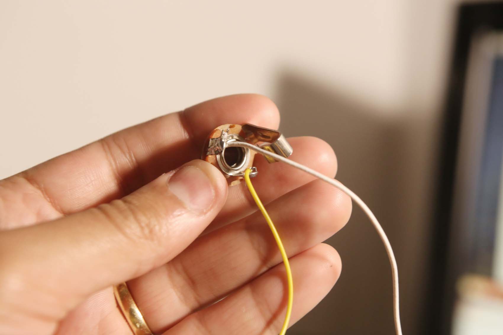
The long lug is live, and the circular plate is ground - so solder a wire with a crocodile clip to ground, and then solder a wire with the capacitor soldered on - either way, as it's non-polarised - to the live lug. You might want to use electrical tape or heatshrink wrap to cover the point-to-point connections you've just made.
Ready to try this on a fuzz circuit? Don't worry, vero and PCB are a lot easier to solder than point-to-point. Good thing you had those helping hands...
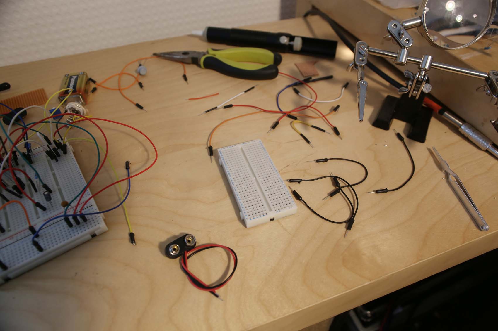
First fuzz, part 1: parts and explanation
For our fuzz, we're going to build pretty much the most simple fuzz circuit possible.
Why it works is beyond the scope of this article, but the 'Bazz Fuss', also sometimes called the 'Bazz Fuzz' is a very square-wave fuzz that's become a staple of the modding community for experimentation and hacking due to its simplicity.
We've adapted the original slightly to our tastes, and a quick web search will show you all the possibilities that are available.
The parts you need are:
- 4.7uF radial polarized capacitor
- 1N914 diode
- 10K resistor
- MPSA18 Transistor
- 22nF non-polarized capacitor
- 100k linear potentiometer
- 9V battery clip
- Two Neutrik jacks
About 10 parts. Not too scary - let's look at how they fit together.
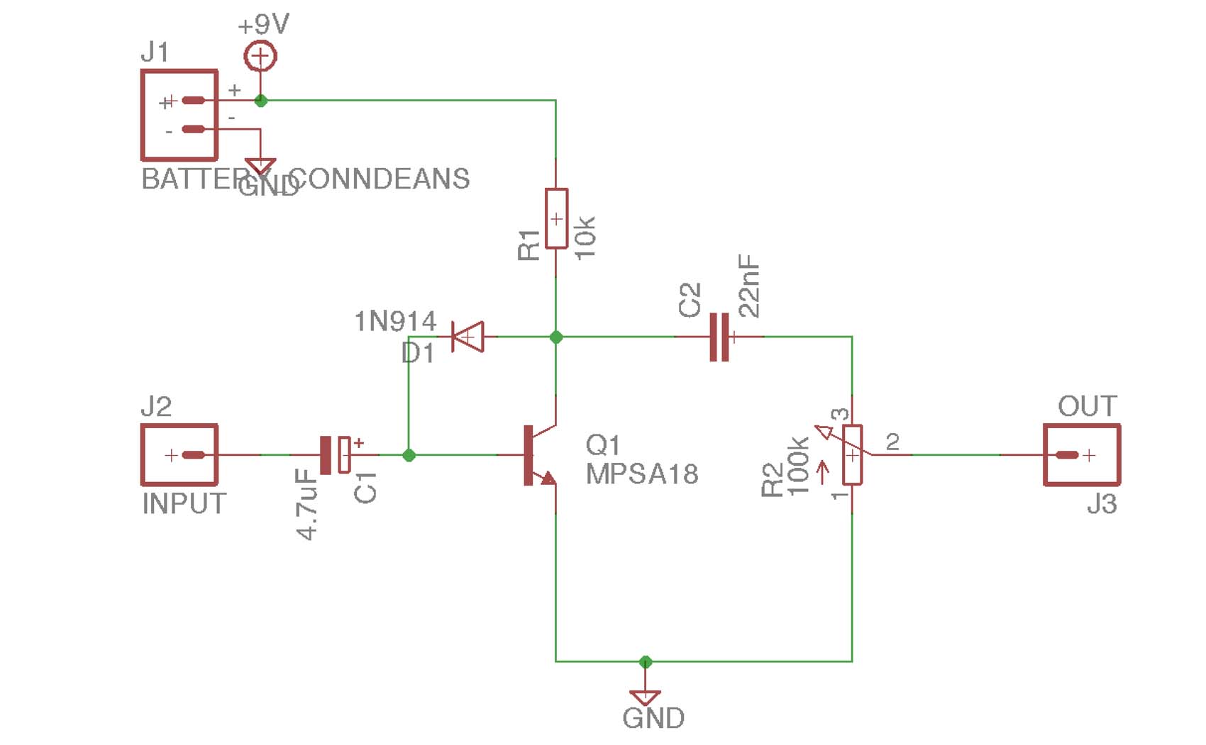
First fuzz, part 2: schematic
On the top-left, we can see our battery. R1 is biasing the transistor Q1, and D1 is clipping the signal in the feedback loop.
C1 is the input capacitor. This capacitor and C2 will act as filters for the signal. R2 is the volume pot, controlling the output level.
If you substituted a Darlington transistor such as the MPSA13, you'd get the pedal to move from more 'synth' fuzz territory into more traditional silicon Fuzz Face territory. Changing the diodes used can help in this as well.
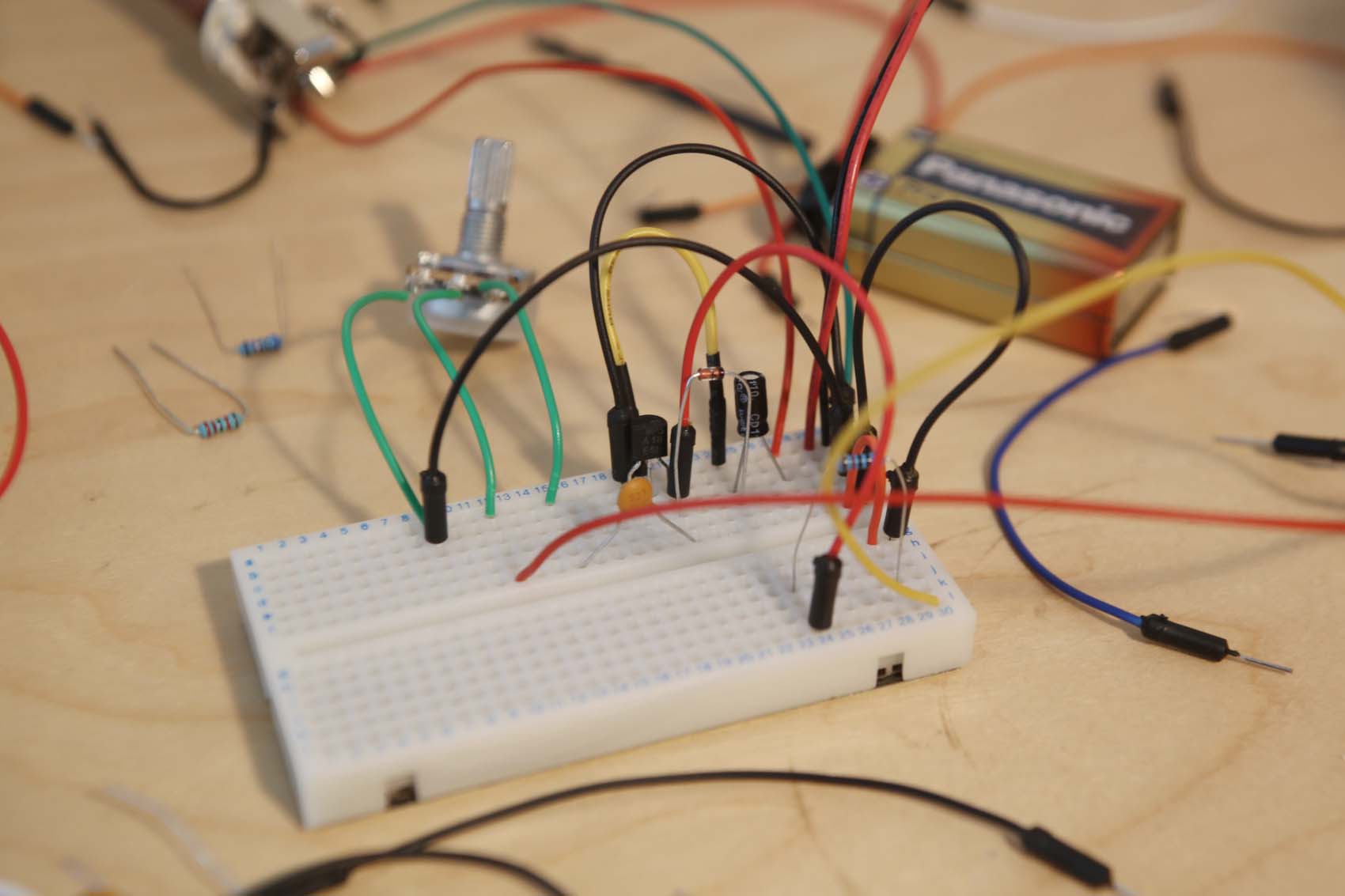
First fuzz, part 3: breadboarding
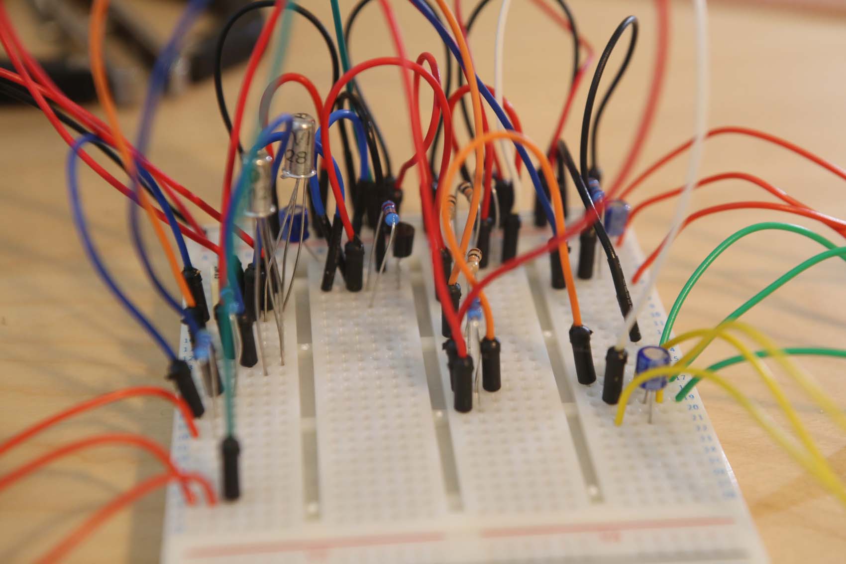
Using a solderless breadboard, we can assemble our circuit without worrying about mistakes.
If your breadboard has a power bus, indicated by parallel red and black lines, you can use this as the live rail (9V) and ground across the board. These two rows are often referred to as the live and ground bus.
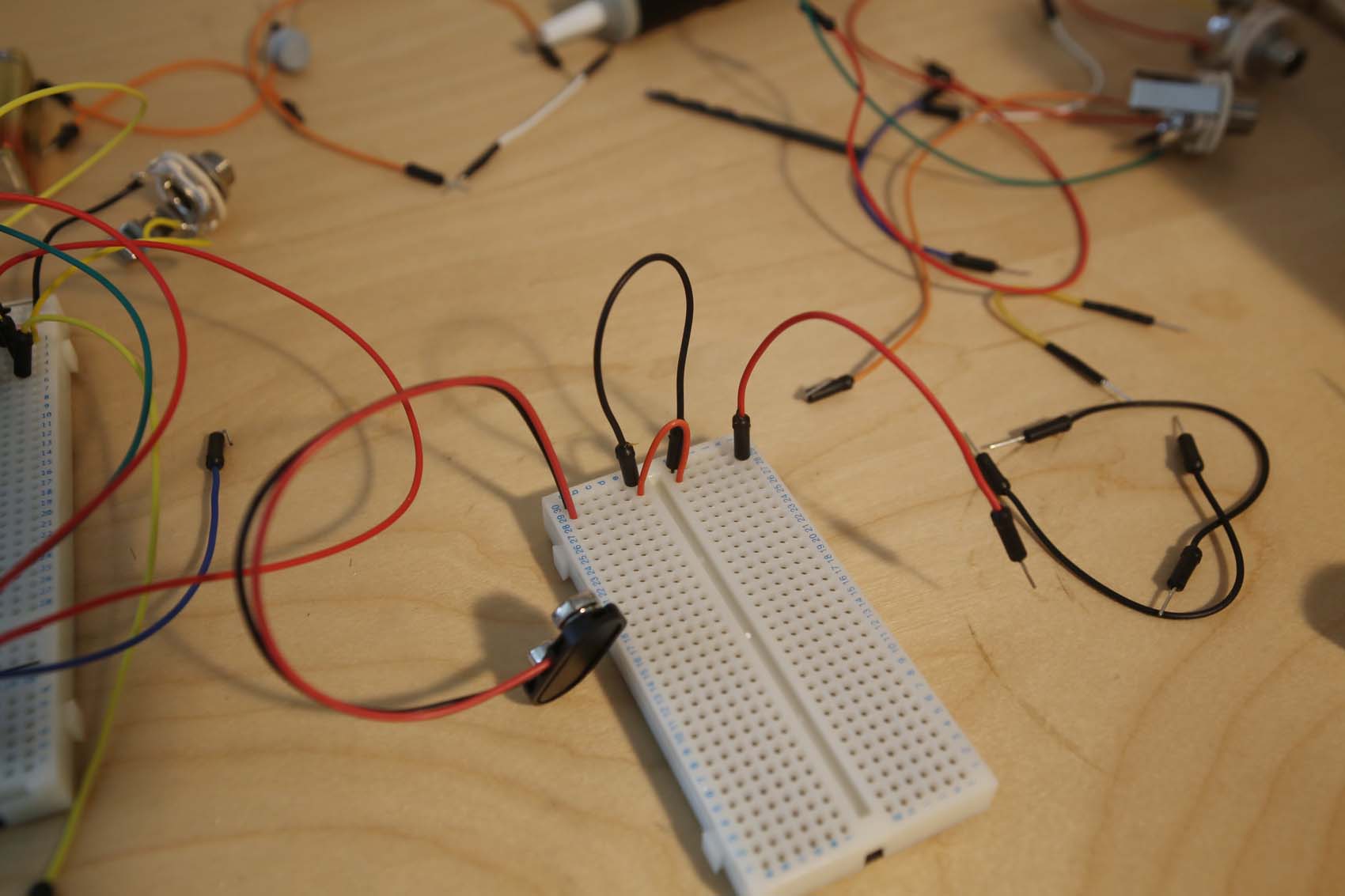
First, connect the battery clips to the power bus - red to red, and black to black. On the breadboard example here, we've created our own bus along rows one and two using jumper cables to carry the current over the break in the centre.
Then place the capacitor in the circuit. Once this is in, put the jack in ground wire in the ground bus, and the live into the same row as the capacitor.
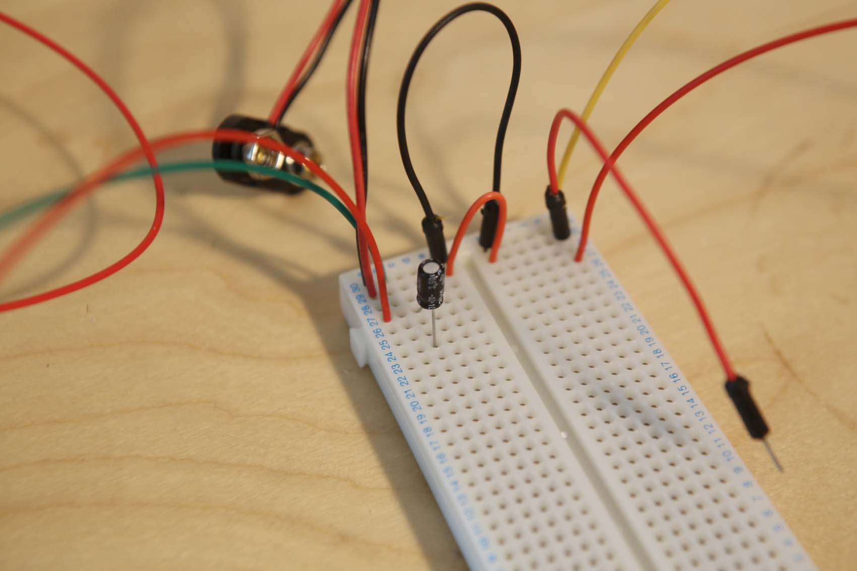
Now, place the MPSA18 onto the left-hand side of the board, with each leg on a different numbered row. On the flat side, the legs should go emitter-base-collector, going from left to right.
Put the positive (anode) leg of the 1N914 diode D1 on the same row as the transistor's collector. Then, place the cathode leg on the same row as the anode of C1. The cathode of the diode will be marked by a black or grey stripe around its barrel.
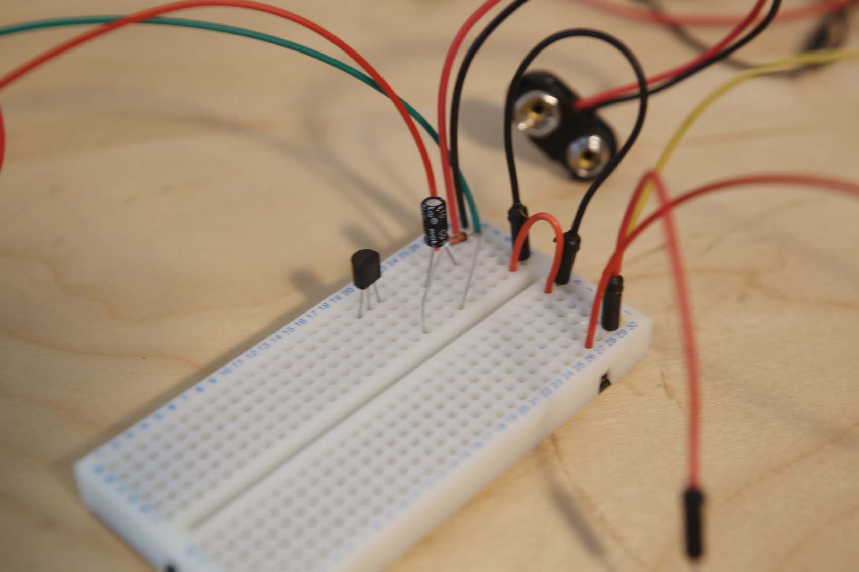
Use a lead to connect the row that the positive (anode) leg of the input cap C1 is on to the row that the base (middle leg) of the transistor Q1 is on. Use a second lead to connect the emitter row (left hand leg) to the ground bus. Finally, use a lead from the collector (right hand leg) row to a new row on the other side of the breadboard, near the power bus.
Here's where our 10k resistor R1 will go. One leg of R1 should go on the live bus row, and the other should go into any hole on the row of the lead we just added. Resistors are non-polarized, so it can go either way.
Nearly there!
Finally, again from the transistor's collector row, add C2. Put its other leg on a new row. On this row, add the lead connected to pin 3 (the right-hand pin) of the volume pot. Pin 2 (the middle pin) and pin 1 (the left-hand pin) should each go on a row of their own.
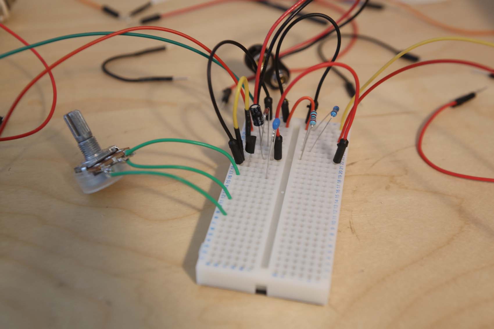
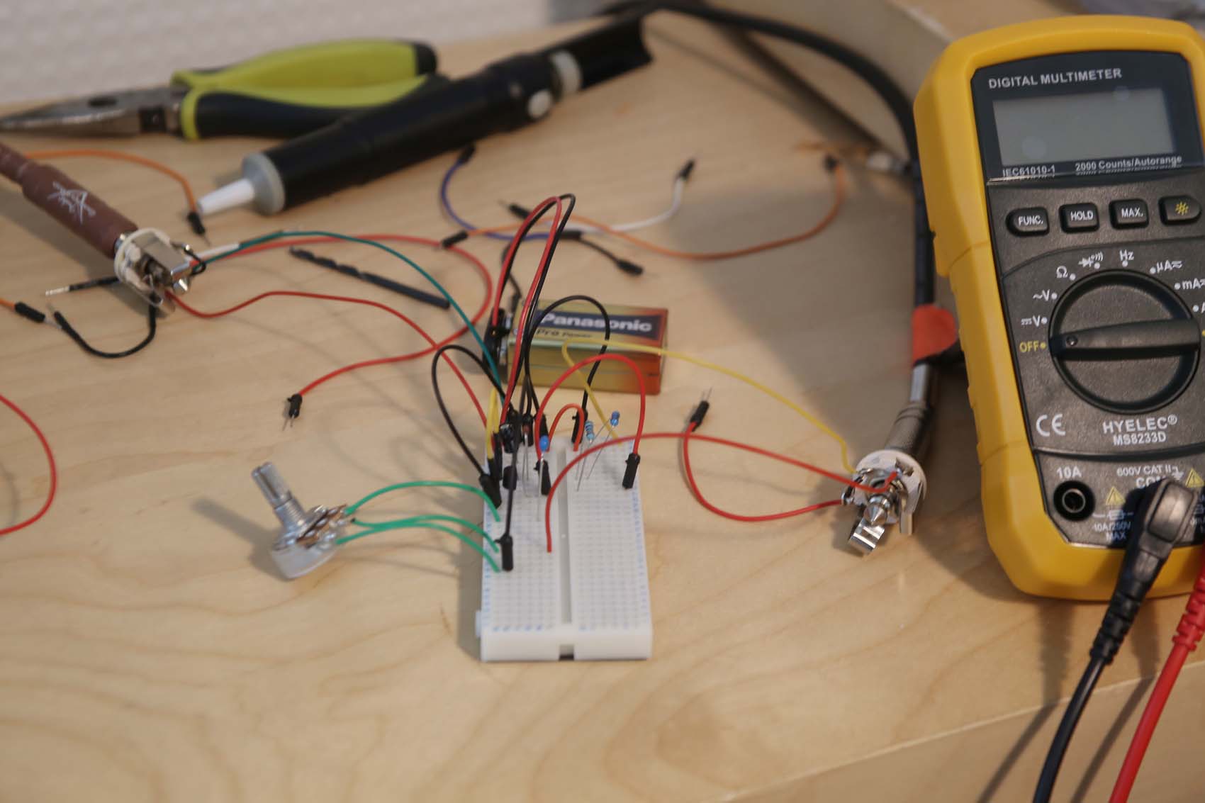
To finish the circuit, connect a lead from the row of pin 1 to the ground bus, then add the output jack. The ground on the output jack goes into the ground bus, and the live goes on the same row as pin two of the volume pot.
Connect a guitar and a battery, crank the volume and enjoy your handiwork!
First fuzz, part 4: putting it all together on vero
Vero, known as strip board or trackboard, is different only in that the strips are longer than your breadboard; this often means that for efficiency you'll end up rotating your circuit to fit.
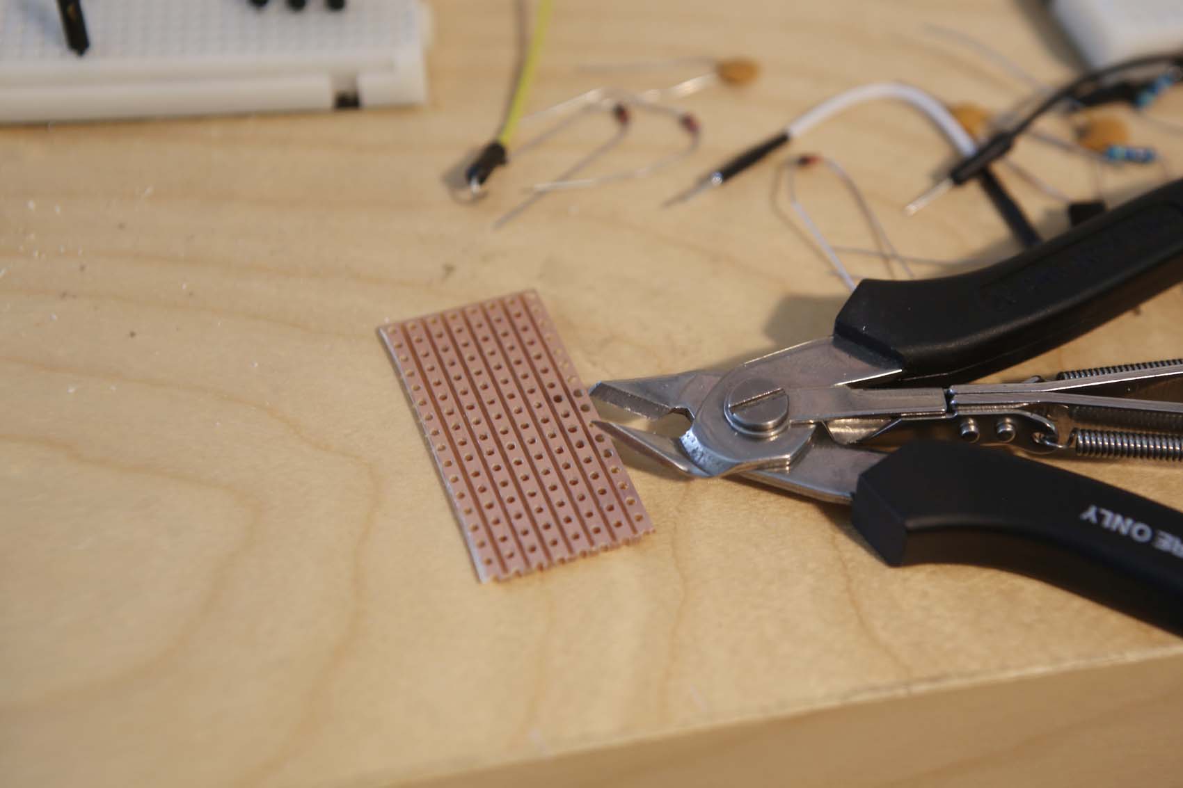
We used a conservatively large piece to make this circuit, using a 6x12 hole piece of vero - for a challenge, you could make a much smaller arrangement if you wanted. You can use your craft knife and edge cutters to clip the vero down to size.
It will sometimes be necessary to break, or 'cut' a track in order to not have current flow where it is not desired. To do this, simply flip the board to expose the copper track, then twist a small drill bit in the hole until it has torn up the track and broken the strip. Brush away any remnants of the copper so they don't cause shorts.
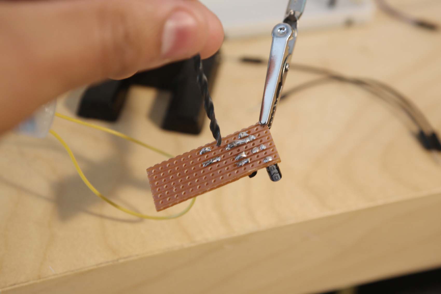
We've deliberately made the layout include a cut to illustrate this concept. We're not going to follow this circuit step-by-step, but rest assured: if your breadboard works, then this circuit will, too, so long as you lay it out carefully.
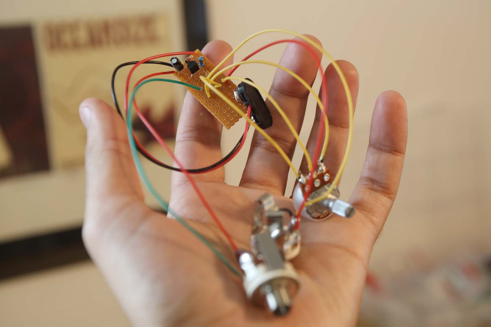
Arrange your parts in place, then use your helping hands to hold the vero in place while you solder the components. Clip any protruding legs using your edge cutters for a tidy finish.
Once you've finished soldering, connect your battery, guitar and amp, and riff to your heart's content.
Wrapping up
Phew, you're all done. Boxing your fuzz, attaching a 3PDT switch, DC in and decorating it is another story, but here's a brief overview.
You’ll need to drill an enclosure with five holes - two for the jacks, one for the DC in, one for the volume pot and one for the bypass switch. A stepped drill bit and a decent drill will help immensely, as well as a vice if you have one.
Before you box your circuit into the drilled enclosure, however, it will need some changes.
Desolder the 9V battery connections and attach a 9V centre-negative DC plug to the correct poles on a 3PDT switch; if you’re not sure where to start, purchase a PCB for this online or search for the correct wiring layout. Lead a live and ground wire out from your switch to your vero, and solder them in place where the 9V battery clip was previously soldered in.
Then, desolder the jack input and output. Wire the 3PDT switch such that the jack in and jack out are connected to it, and make a circuit in wire and circuit out wire connect to the in and out pads on your vero. These should correspond to the live wires from the jacks - the ones that were not connected to the ground bus.
Once you have done this, you will be able to wire in an LED battery indicator to the bypass switch - although remember that it will need a resistor and a hole in the enclosure to accommodate it.
If you're itching to get started on a more complex circuit, you probably want to breadboard it first (as you can see above), or order a pre-fabricated PCB from the internet, if it's a clone or common circuit. For our money, Fuzzdog's Pedal Parts makes some of the best clone PCBs.
On the other hand, if you want to learn more theory, here's some good resources to start your journey:
The technology of the Fuzz Face
Wampler Pedals Breadboarding Basics Video
Happy hacking!
Alex Lynham is a gear obsessive who's been collecting and building modern and vintage equipment since he got his first Saturday job. Besides reviewing countless pedals for Total Guitar, he's written guides on how to build your first pedal, how to build a tube amp from a kit, and briefly went viral when he released a glitch delay pedal, the Atom Smasher.
