How to rewire a hollowbody guitar
How to ace the dreaded task of re-wiring a 335 without easy access

Whilst they’re lovely to look at and play, the ES-335, Casino, Riviera, Sheraton, Dot and a whole host of Jazz boxes are a right pain to re-wire. Even though it’s often the same circuit as a Gibson Les Paul, the lack of a rear access panel makes it harder to install or repair.
There are two unique features that need to be catered for to do a professional job on a hollowbody guitar. Firstly, the wiring needs to be screened so that no humming can enter the circuit. Secondly, no wires should cross the F-hole spoiling the look. Easy... right? To repair this circuit it’s often best to take out the whole kit and caboodle - without scratching the paint job, of course. So, with the help of some hair-brained techniques and pre-planning we’ll show you how to do this.
Our patient today for keyhole surgery is a rare Maya 335 copy (complete with mad tremolo) whose vital organs are showing only signs of life from one pickup.
What you need:
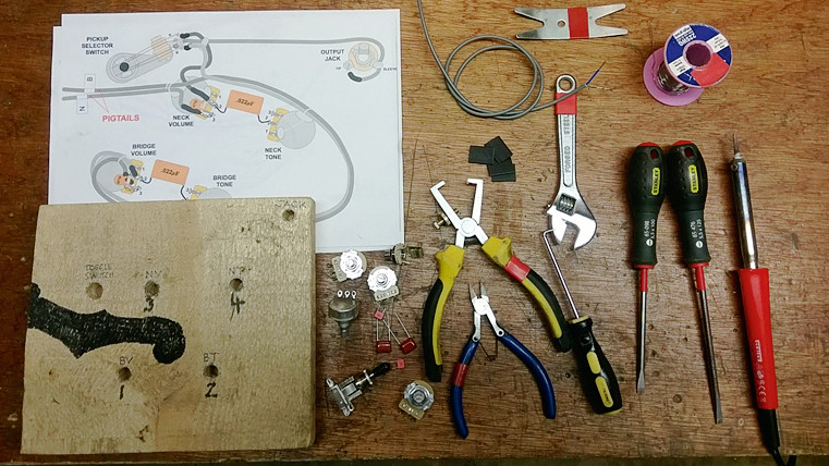
- Wiring diagram
- Assembly board (wooden block or stiff card)
- 40W soldering iron
- 60/40 solder
- Screened cable/ braided cable
- Shrink tubing
- Lighter
- Wire strippers
- Wire cutters
- Flat head screwdrivers selection
- Hook and pick set
- Adjustable spanner
- Steady hands
- Patience
Step 1
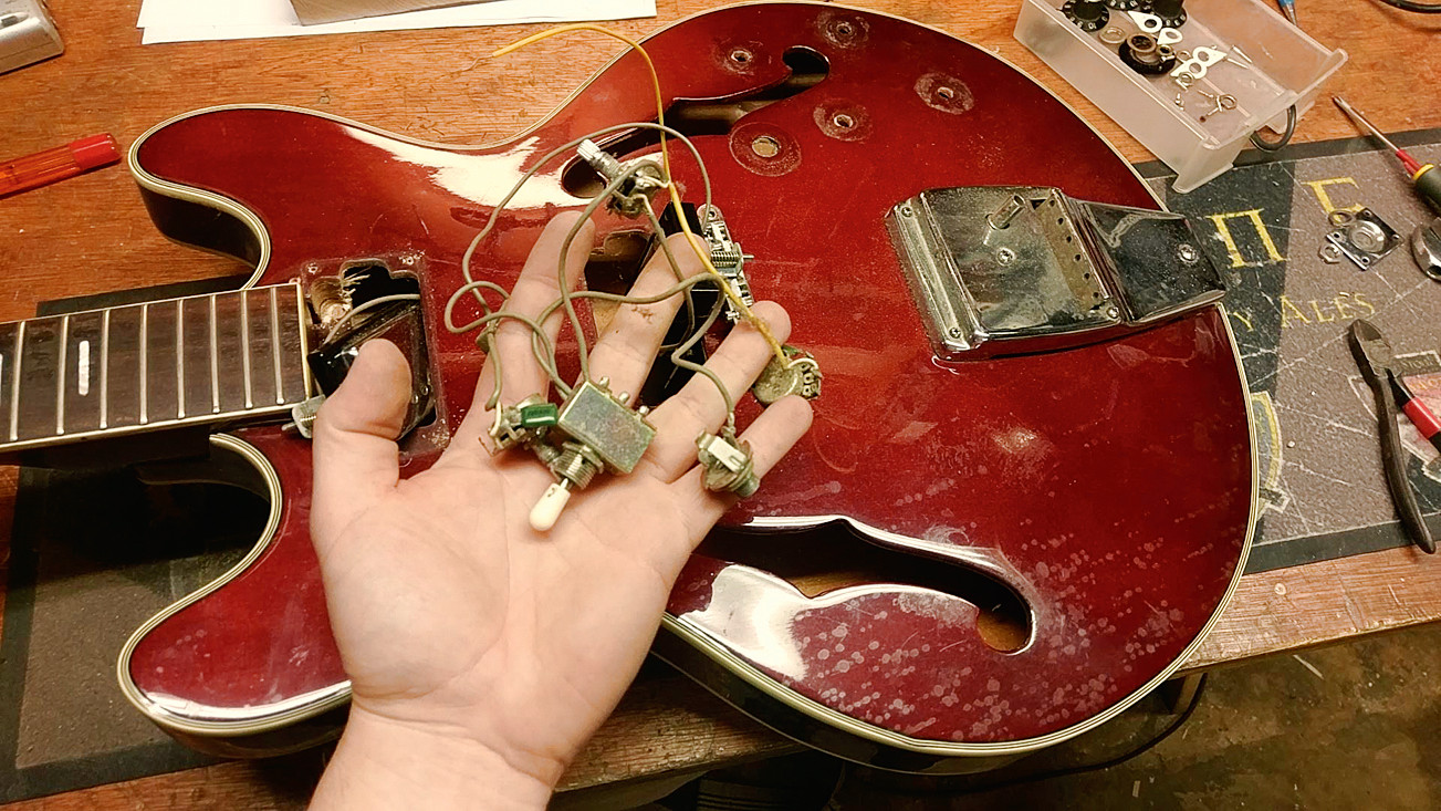
As only the bridge pickup was giving output, let's pull out all the old guts. To do this, you must undo all the nuts hiding underneath the knobs, the pickup selector switch and jack socket. There’s one wire left inside which is the bridge earth wire - attached to the bridge or tailpiece, snip that fella off at the pot.
Step 2
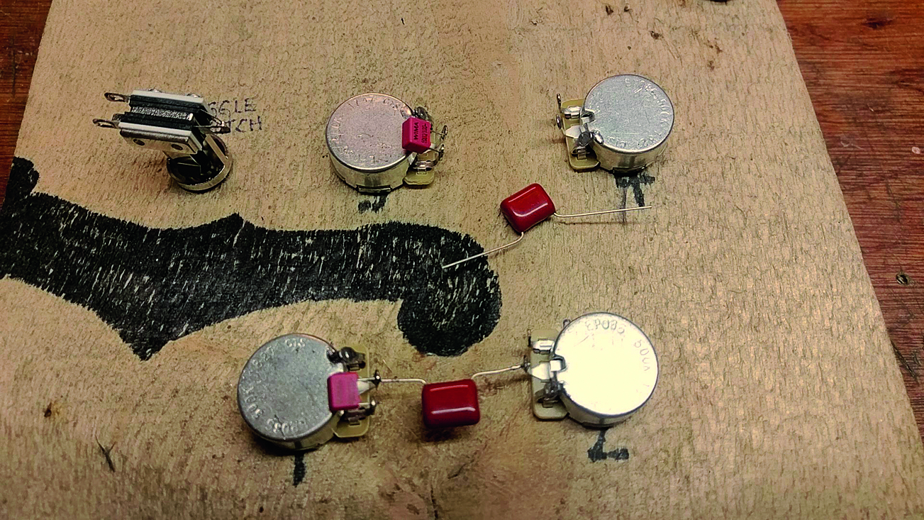
This soldering template is handy: we recommend making one out of wood or card. It’s the exact spacing of the guitar and mirror-imaged - we’re soldering it upside down. The F-Hole has been drawn on too so we know not to cross it with a cable. Pop in your components, add your capacitors and solder the earth legs to ground.
Step 3
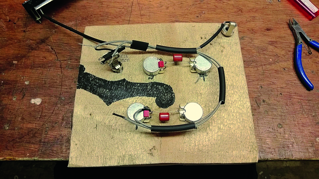
We’re avoiding the F-hole because we don’t want any wires on show when we’re done. The black tubing is heat-shrink and helps to hold the cables in the right shape and also offers insulation. The bare braided wire often needs insulating in case it short circuits something. We’re opting not to solder any grounds on yet.
Step 4
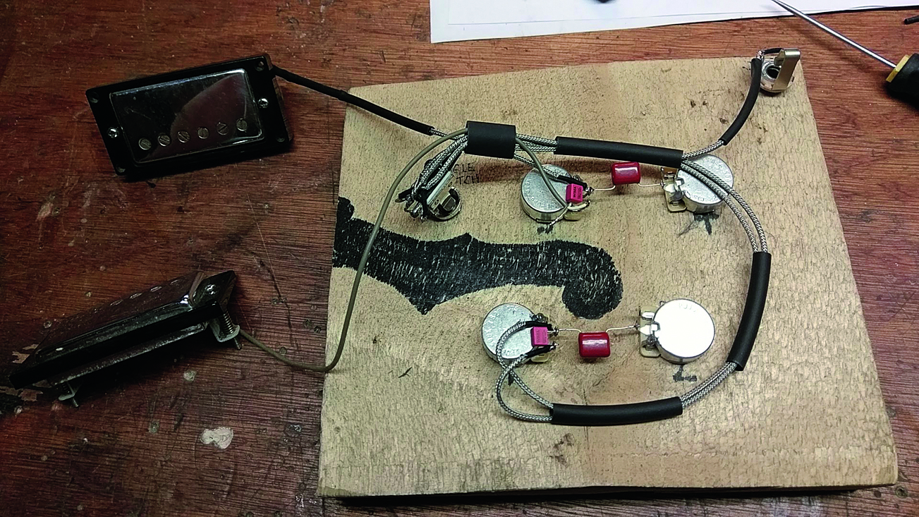
That’s the whole circuit in place apart from the ground connections. Can you see we’ve used exactly the right amount of cabling so that the wires will install easily? The circuit gets a little stiffer the more cables you add. One of the pickup wires uses a plastic jacketed wire which has been kept separate so it doesn’t melt.
Get the MusicRadar Newsletter
Want all the hottest music and gear news, reviews, deals, features and more, direct to your inbox? Sign up here.
Step 5
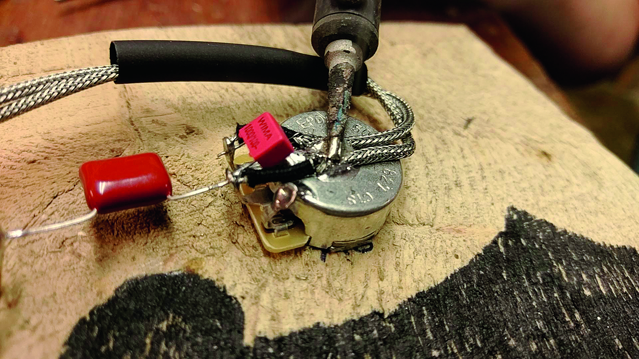
This is a step unique to the bare braided wire - it has a cloth-covered wire inside which will not melt. This is how Gibson solders theirs on. It takes a bit of time and quite a lot of solder to get these looking nice. Be careful as the whole pot gets very hot at this stage.
Step 6
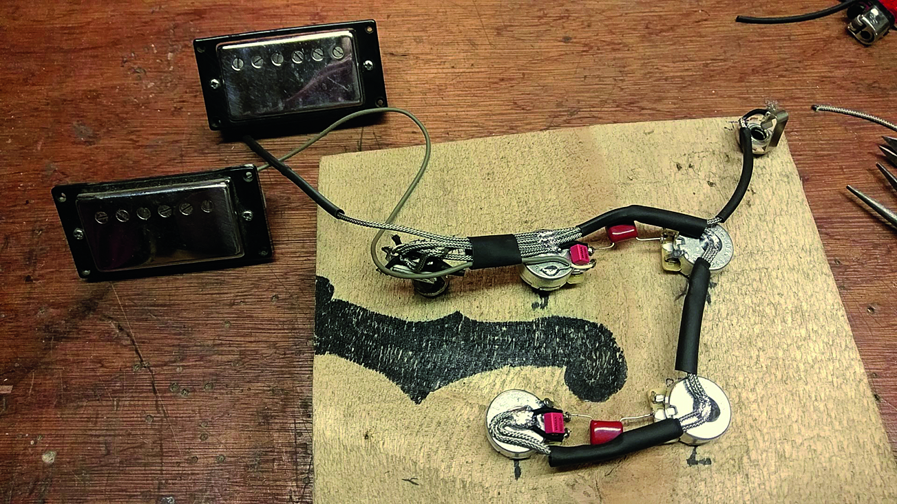
Soldering the braids on gives the final shape and structure to the wiring as well as of course completing the circuit! The shrink tubing can now be shrunk by heating it up with a lighter. There’s one more thing left to solder, so keep the soldering iron on.
Step 7
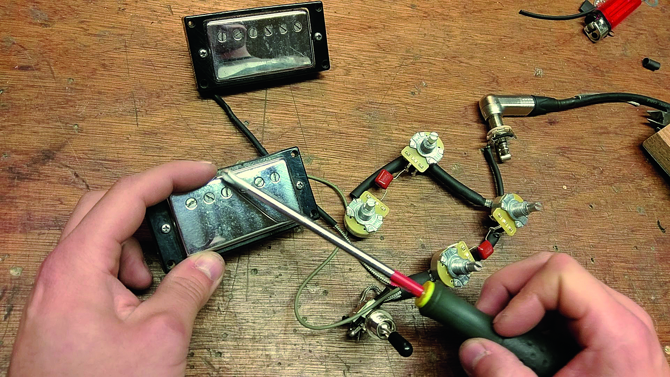
We’d be mad not to test it at this stage! Plug into an amp and check the functions by tapping gently on your pickups with something magnetic. You can test the function of the volume and tone pots. Test potential short circuits from the braided wire - make sure it’s not able to touch parts of the switch, jack socket or pot legs.
Step 8
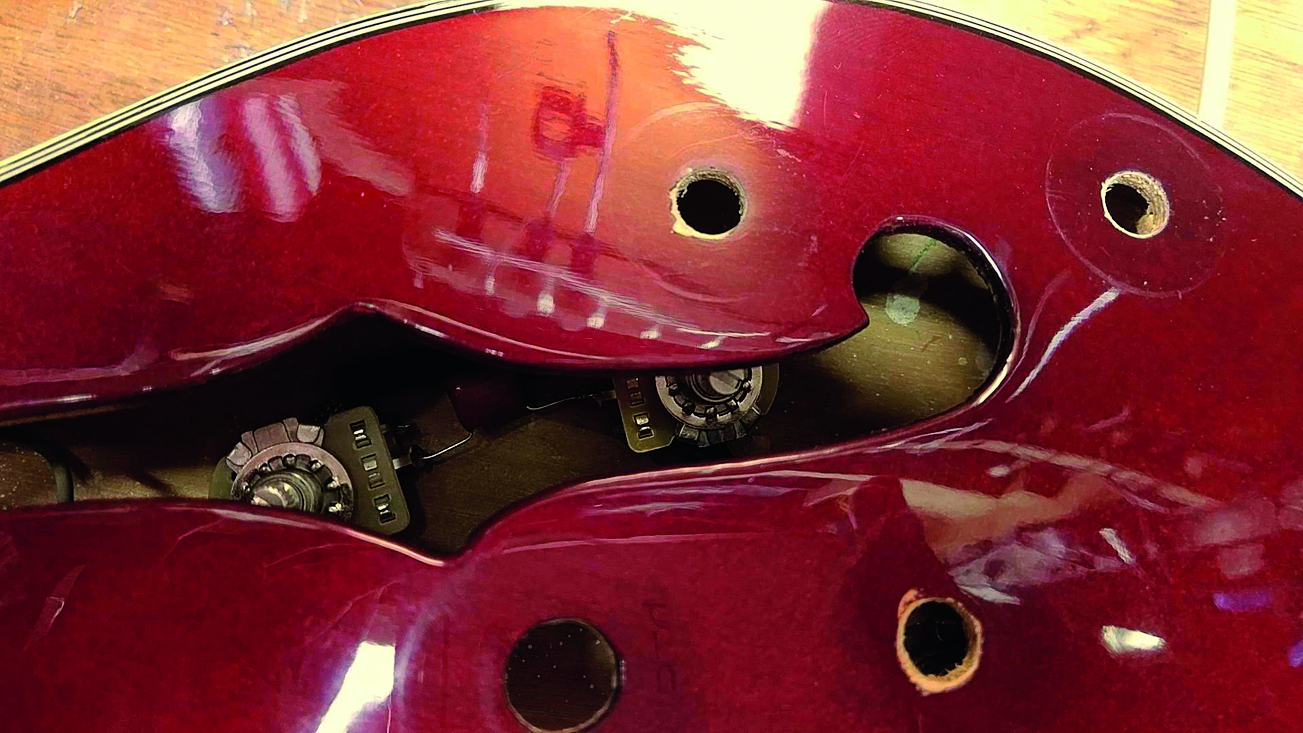
Because your soldering board was made with great care, it means installing the wiring loom will be easier... still challenging, but easier. Feed in your circuit through the bridge pickup rout keeping tabs on what pot is what. Keeping the pots the correct way up, it’s now time to put on the pots’ star washers.
Step 9
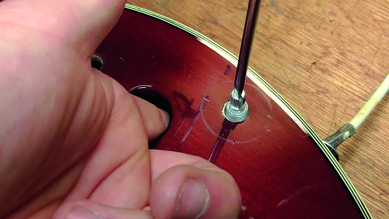
Start with the bridge tone pot, the easiest one to install. This can be done with a finger and a little help from a screwdriver. You can hold the pot in place with your finger whilst you add the washer and nut. Fiddly hey? Makes you wish they just had an access panel on the back.
Step 10
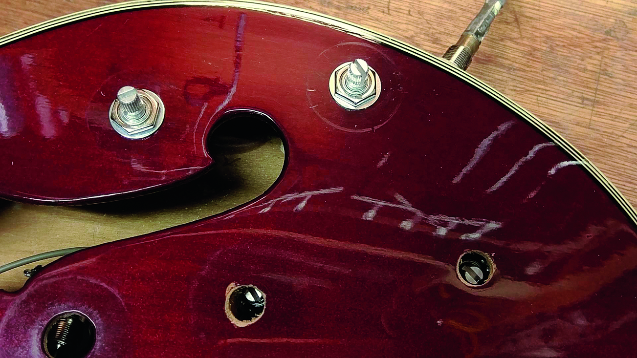
At this stage only fasten finger tight. Here’s our technique: with the pot below a pot hole, use a flat head screwdriver to gently jab in between the tabs of the pot shaft. Lift directly up. Use a finger to push it to the side to jam it while you get the washer and nut on with the other hand. Don’t drop it!
Step 11
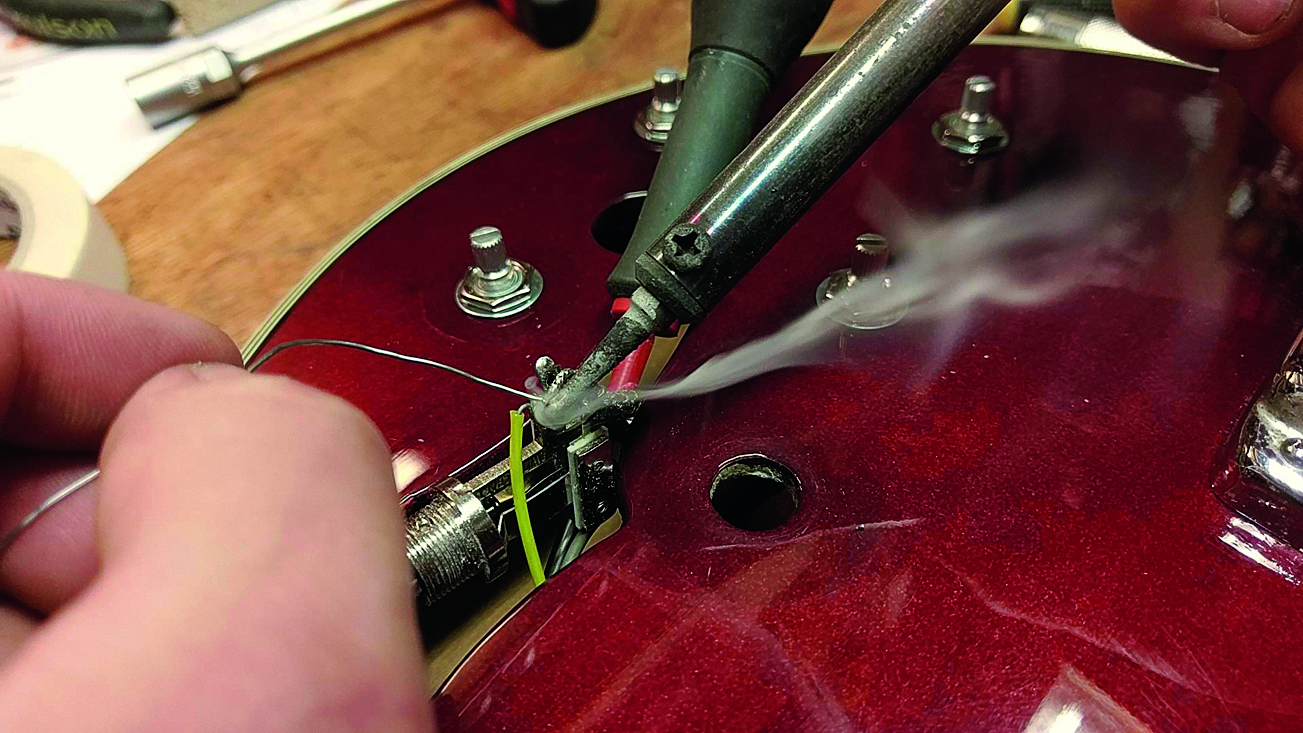
Now the last bit of soldering then you can turn the iron off. This is that bridge ground wire. The easiest place to install it is the pickup selector switch; join it onto ground there making sure that it cannot touch any of the live parts. We found it handy to hold it in place by wedging the switch upwards with a screwdriver.
Step 12
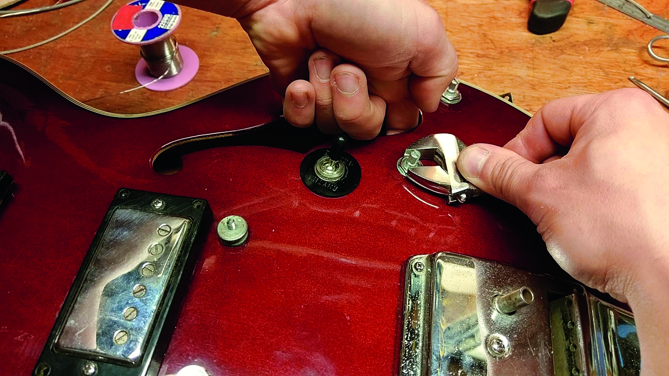
Test it again by tapping the pickups. Hopefully nothing’s snapped off or short circuited... you’d have to go back if it has. If you passed the test then tighten up the nuts whilst supporting the pots as best you can. If you just crank them round the pots inside may spin causing problems. That’s it - fit your knobs and away you go!
Jack runs an independent guitar setup and guitar repair service in Manchester, England. He serves the musicians of the Northwest of England, working on electric guitars, bass guitars, acoustic guitars and more. Jack has been writing the Fix Your Guitar column in Total Guitar Magazine since 2017.

