The producer's guide to DIY modular
Rob Redman shows you how to break out the soldering iron and build your own modules
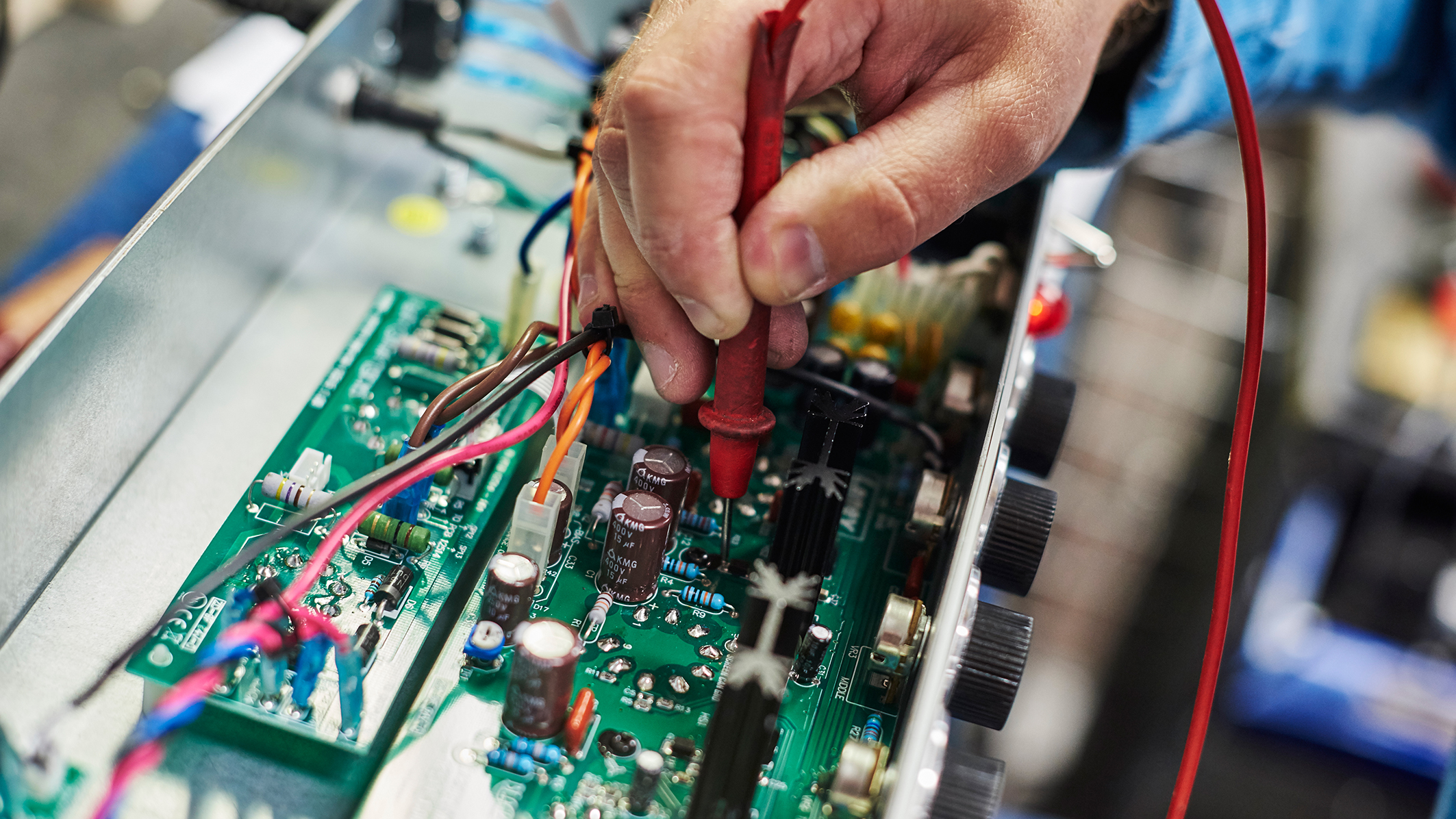
There are many reasons to embark on the DIY module journey. It could be a simple case of saving some money, or maybe you want to understand the components that go into your favourite modules. Maybe you have an idea to develop modules of your own but don’t know where to start.
Today we’ll be discussing the basics of this weird science, showing you some key techniques and highlighting some of the tools and components that are needed to get started. Grab a cuppa and a magnifying glass and let’s get started…
It's all in the mixer
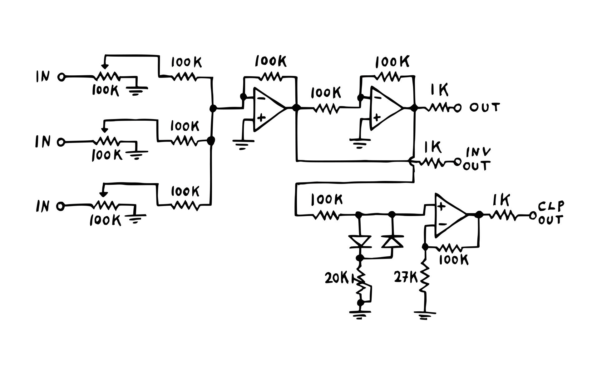
Designing a module is outside the scope of this article but it’s worth exploring how circuits work in the context of a synth. We’ll focus on a simple mixer module, from Erica Synth’s DIY range. What’s interesting with this very simple circuit is the addition of diodes, used to add some distortion to the output. Or, as is the case here, a separate output for the clipping circuit, which makes this a more versatile module than it might otherwise have been.
So what’s a mixer? The idea here is to take two or more incoming voltages and mix them together, to create one new voltage. The problem here is that without some form of control you’d always output the average of the two signals, so we need to add attenuators, or potentiometers, before the mix happens, so we can dial in how much of each is used.

Best Eurorack modules: essential oscillators, filters, utilities, effects and more
But what about the distortion that makes this module extra useful? This is called diode distortion and is why there are two op amps in the kit. Once the mixing stage is complete, the signal will go to the output but in this circuit the signal also goes off to the distortion section. Here the current hits a diode, which stops the flow of current in one direction.
A trim pot (basically a variable resistor) is used to dial in how much voltage hits the diode, which needs a certain amount to start opening and letting current flow through it. Resistors are used to control when and how much this happens. The outgoing current is then amplified by an op amp which is protected by a diode before being sent to the ‘clip’ output jack.
This is only part of the story and, while simple, the circuit has a bit more going on, so check the schematic to fully understand what’s happening, as lots of other components influence the flow of current. When you check the BOM (bill of materials) it can be worth having the pcb to hand, so you can think about what goes where. A method of keeping things organised can also be useful, even if it’s just small tupperware boxes with labels and a good organiser is essential; buying components in bulk can be very cost effective.
Get the MusicRadar Newsletter
Want all the hottest music and gear news, reviews, deals, features and more, direct to your inbox? Sign up here.
Handling a soldering iron
Build some best practices for your main tool, to make sure you work safely and get the best results
Soldering is one of those tasks that many find daunting. Understandably so, as there is high wattage, high temperatures and small components involved. However, the reality is far from complex. The process itself is relatively simple and with a little muscle memory and a few tips for success you’ll pick it up in no time.
When it comes to choosing a soldering iron go for the best you can afford but don’t worry too much if your budget doesn’t stretch that far. When you spend more you get benefits like control over temperature and often a more consistent power supply but even a cheap iron will suffice. A solder sucker is a cheap but useful tool to have at hand too; it can help in remedying mistakes if they happen.
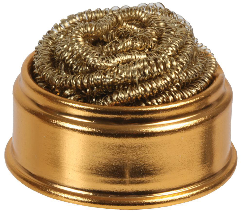
Keep your soldering iron’s tip clean. You can get away with a wet sponge but that can reduce the tip’s temperature, so a tub of brass wool is best. Simply push the tip in a few times to remove debris, then coat it with fresh solder to keep it in best condition.
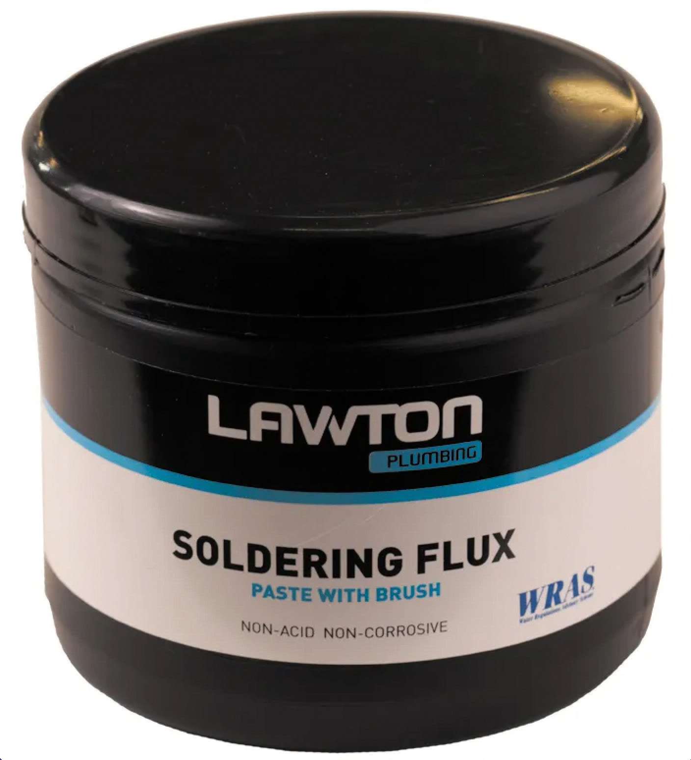
Use a little flux to keep temperatures consistent. During use, the tip can oxidise and a little flux can eliminate that. Then retain the tip and you’ll find temperature transfer remains even, making it much easier to solder your components to the pcb.
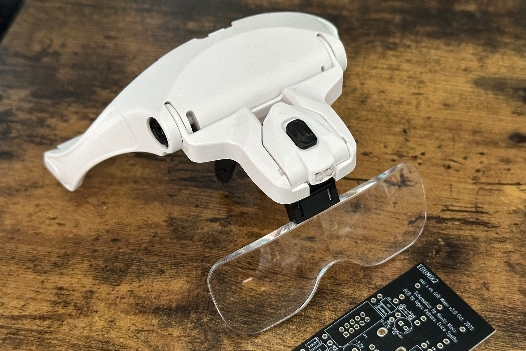
When using a premade pcb, which we’d recommend for at least a few early builds, invest in some magnifying goggles and something to hold things in place. The magnifier will help identify what can be tiny labels, avoiding mistakes with placing components.
Four quick tips
1. Whether you’re working in a dedicated workspace, or simply at the dining room table in your spare time, keep the area well ventilated. Soldering can produce some nasty fumes, so protect yourself and those around you while you work.
2. Get yourself a breadboard. These are basically like a printed circuit board but temporary, allowing you to plug components and wires in to test concepts and are really useful and cost effective tools for all kinds of electronics.
3. A magnifying glass or goggles can be useful. This can be a huge aid and prevent costly or annoying mistakes when identifying things like resistor ratings, where colour codes can be tiny.
4. A circuit tester is a must for any electronics job. Get the best one you can afford. It will serve you well as well as last a lifetime.
What are they building in there?
Modules come in all shapes and sizes but there are some key components you’ll find in almost all of them. Each of them has its place and task
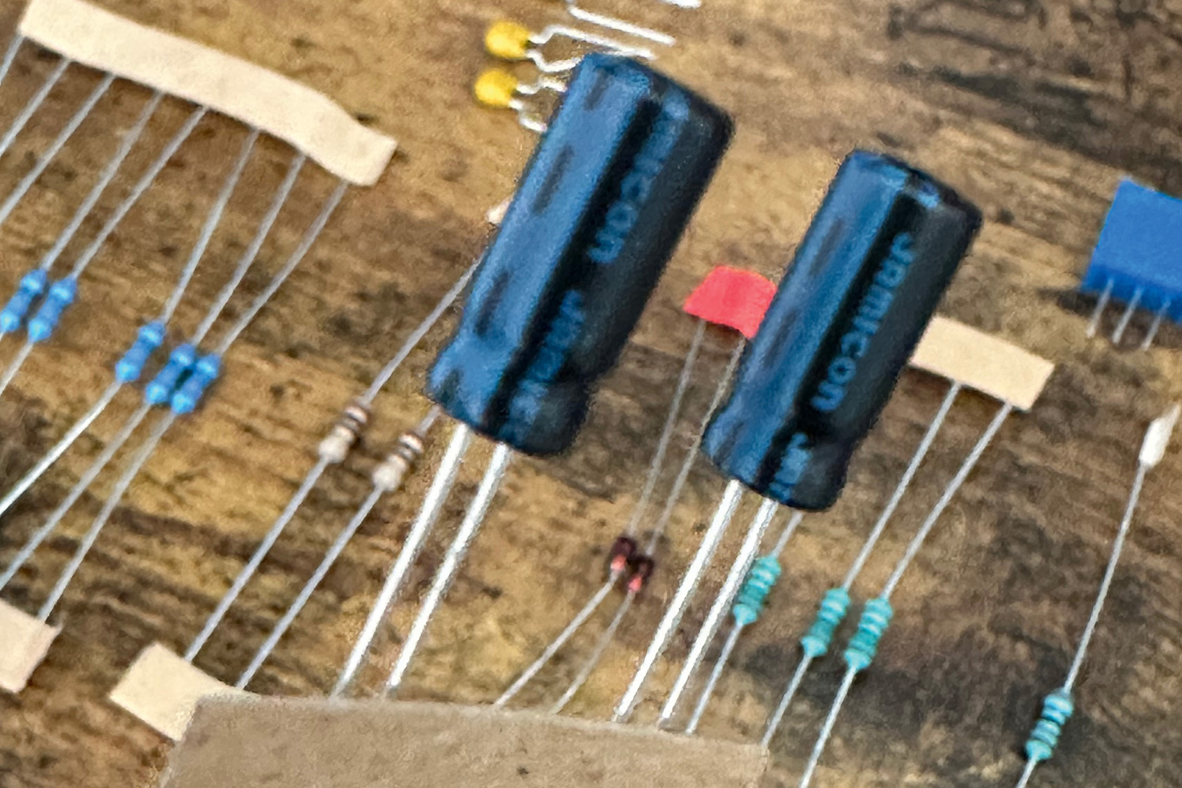
Capacitors. These devices can be found in all sorts of shapes, sizes and materials, from ceramic to electrolytic. They have many uses from splitting AC/DC to being a fundamental part of a filter but essentially they store current and this can be used for many things from power circuits, through to noise reduction and more.
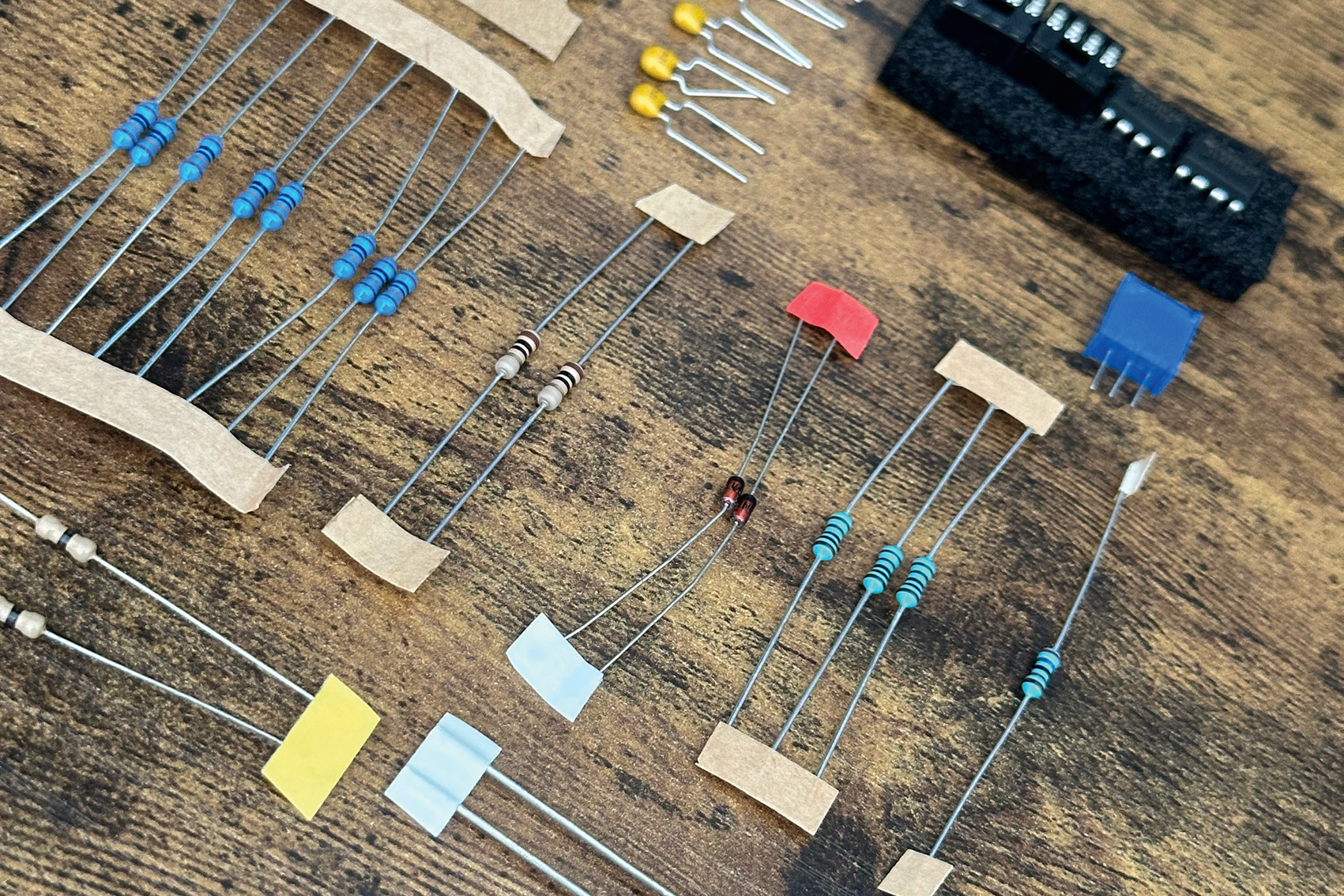
Resistors. These are the backbone of a circuit. They’re available in a huge array of values but they share a common attribute and that is that they impede a current. They are used mostly as control elements, changing an incoming voltage to a different one, with the resistor’s value dictating the level of change.
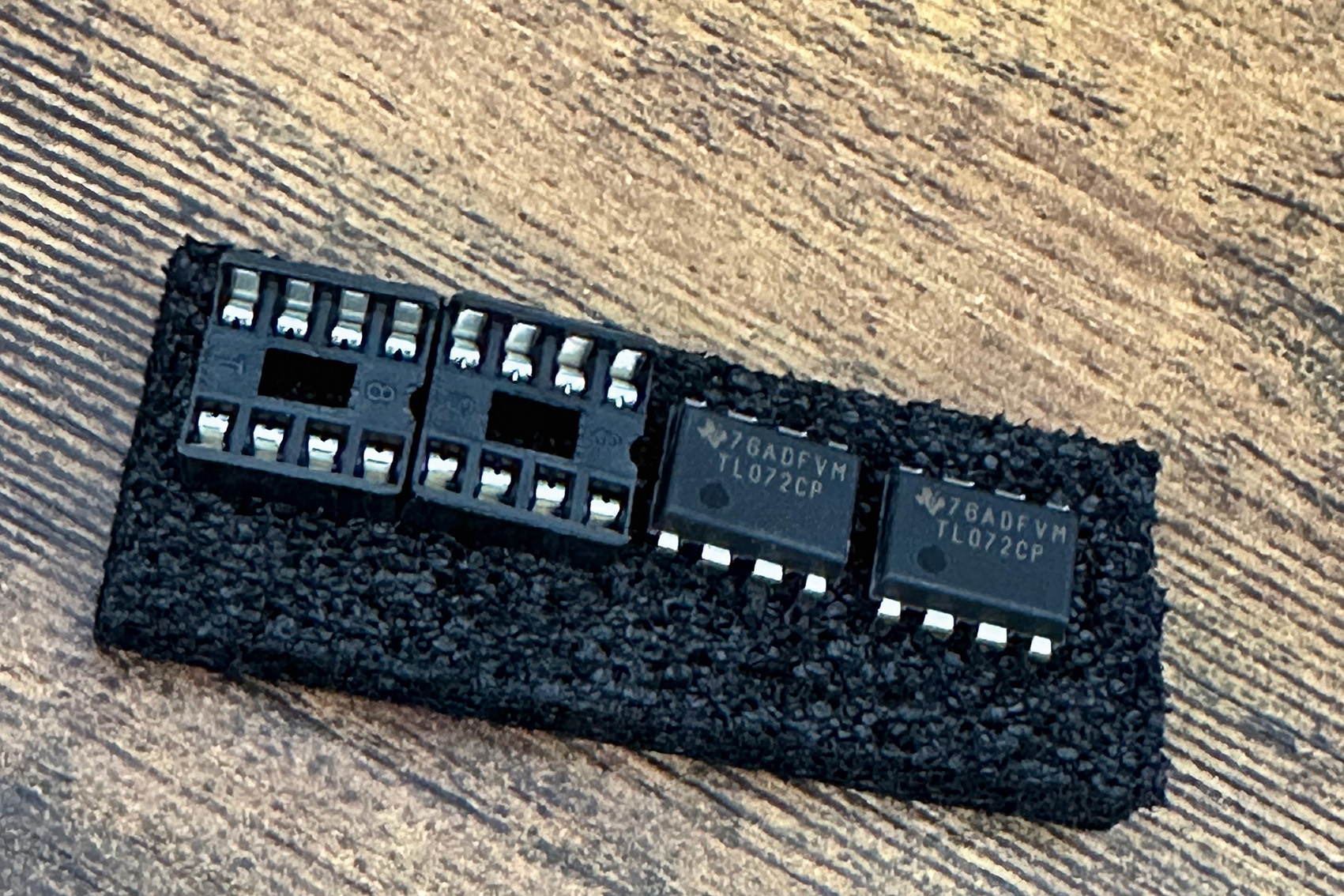
ICs, or integrated circuits, are self-contained circuits that live on a chip. These can be used for all sorts of tasks, such as op amps for distortion, but are mostly used as time and space-saving devices.
Transistors can act as switches or amplifiers. Think of old radios, where they would take the weak signal and boost it so that you can hear that signal through the speakers. When acting as a switch, a small voltage can be sent to the base (one of the three legs) which causes the other two to turn on, allowing current to flow through them.
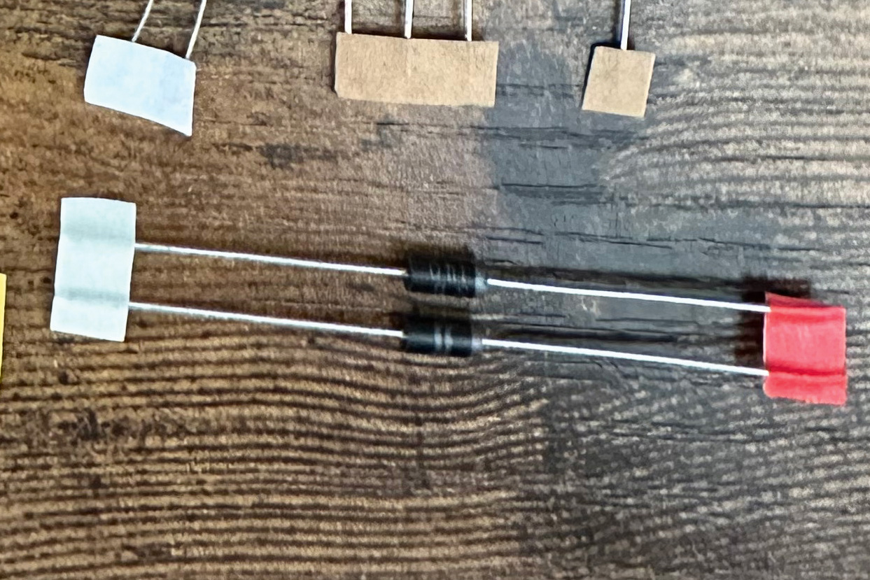
Diodes are basically roadblocks for current. They can prevent current from flowing in one direction, while allowing it to flow in the other. Many components have a positive and negative side. In a diode, this is really important as they are often used to protect sensitive parts of a circuit, such as the ICs used in op amps, or for converting AC currents to DC.
Mounting hardware
How to start low
You may be tempted to start soldering all the larger components first but you should begin with the lowest lying first. It will make your life far easier in the long run and, if you keep things neat, you won’t have any trouble installing everything later. Start with resistors, diodes and small capacitors, working through transistors, larger capacitors, then ICs. When installing, focus on labelling on the PCB, as some things, like diodes, have a positive/negative side – these must be the right way round. If your kit isn’t well labelled, keep a resistor rating chart to hand, to match the pcb, or circuit diagram.
How to work double sided
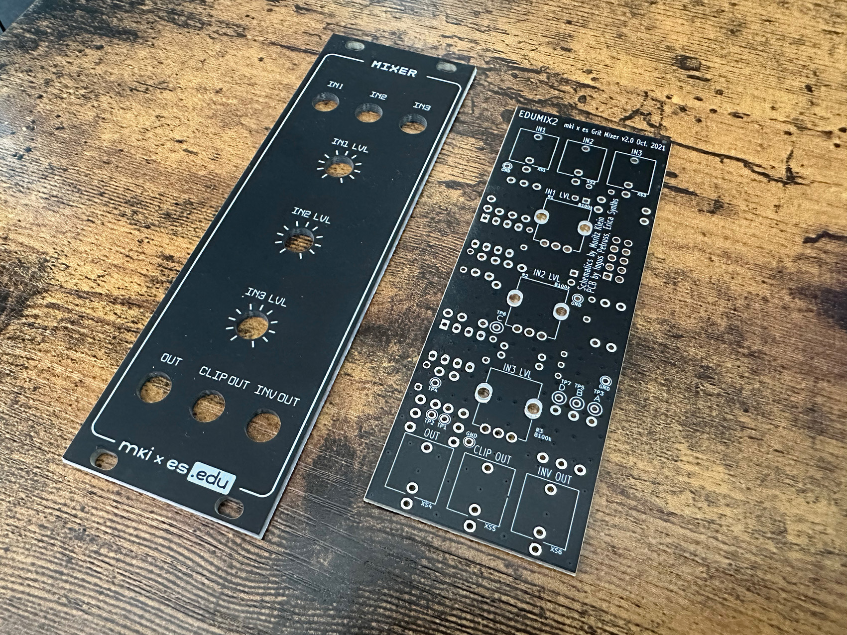
You may have noticed that your pcb has things printed on both sides. One side may be a lot busier than the other but make sure you stick to the correct side. You may well still end up with a performing module if you get it wrong but it may well mean you have to desolder things to get the forward-facing components installed. For example, there may be jack sockets and attenuators, which need to then be fed through the face plate, making it really important for both the build process and the stability of the finished module.
How to get the right end
Some components, in a similar way to polarised ones, need to be installed in a specific way. You will find that the hardware and labelling, as well as some of the mounting points on the printed circuit board, will have a clue as to which way round to place them. The TL072 ICs often have a semi circular notch on one end and the power socket will have a flattened corner. Match these up to the pcb and you will be good to go.
How to test the water
If you’re unsure about any component, then test it. Polarity is so important it’s best not to get it wrong and resistor colour schemes can be tricky to identify. This is where a breadboard can be so valuable. Testing parts of, or even an entire circuit, before you apply any solder, is a great way to both check you have everything in its right place, as well as to get a deeper understanding of what is happening and the flow of current through your module. Circuit testers/multimeters don’t need to be expensive but can save you headaches and ultimately make the whole experience a fun and educational one.
Understanding circuit diagrams
Master the basics of this seemingly arcane language of glyphs, to better understand how components match schematics
An IC/integrated circuit can have a number of symbols but most are a variation on the theme seen here, that looks a little like a square bug. Many will have a notch out of one end that corresponds to the same notch on the printed circuit, so you can be sure it is safely installed in the correct orientation.
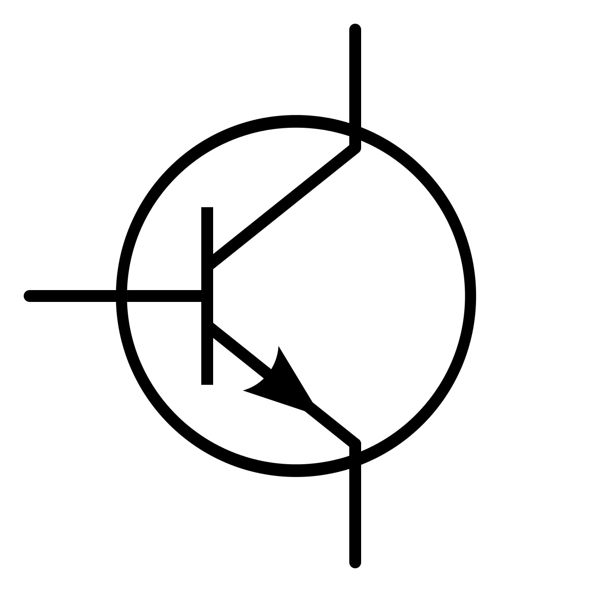
Transistors vary a bit but for most cases have three legs, marked something like A, B and C. B, the middle leg, is the base. The other two are the collector and emitter and you can tell the direction of the flow of current, symbolised by the little arrow seen on the glyph.
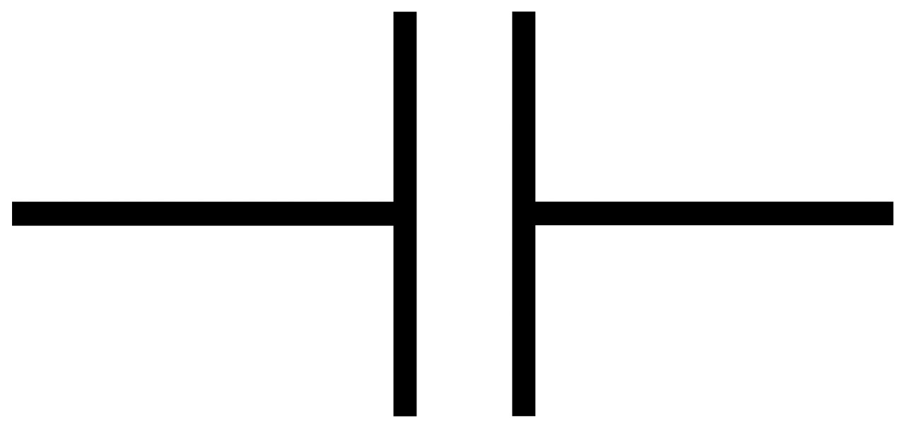
Capacitors have an easily read symbol where two lines break the circuit, running parallel to it, with a space between them. Some polarised capacitors have slight variations showing the negative side. You may see a curved line, or one with the ends angled. The outcome is the same, the straight line is the positive side.
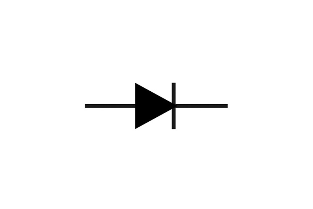
As we’ve discussed, diodes are polarised components and need to be installed the right way. The symbol on a schematic will show a triangle with a line across one point. The side with the line is the cathode, or negative, while the other side is the anode, or positive. On the hardware you will see a line around one end, signifying the cathode.
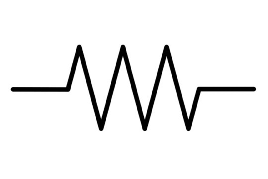
Resistors come in all shapes and sizes and uses, but for the most part the symbols are all based on the sawtooth shape. An attenuator is the same, with the addition of a perpendicular line through it. Then there are some with the sawtooth in a box, usually for protective resistors.


“Excels at unique modulated timbres, atonal drones and microtonal sequences that reinvent themselves each time you dare to touch the synth”: Soma Laboratories Lyra-4 review
e-instruments’ Slower is the laidback software instrument that could put your music on the fast track to success


